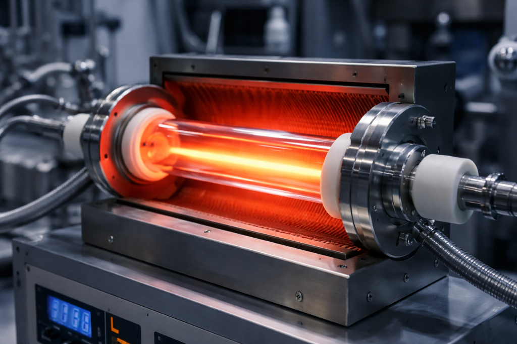
A closed-end quartz tube may look like a relatively simple component.
One end is open.
The other end is sealed.
But for semiconductor process equipment, the closed end is often the most difficult part of the entire component to manufacture correctly.
The sealed tip must maintain:
- Controlled internal volume
- Stable wall thickness
- Smooth geometry
- Low residual stress
- High-temperature stability
- Chemical resistance
- Leak integrity
- Clean internal surfaces
If the tip is too thin, it may become mechanically weak.
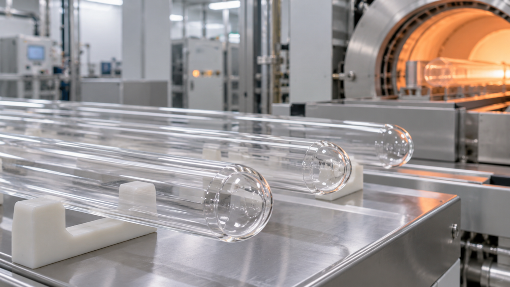
If it is too thick, thermal gradients may increase.
If the transition from the cylindrical wall to the closed end is abrupt, stress can concentrate around the transition region.
And if the tube is used as a protective sheath, gas barrier or process enclosure, even a very small leak can make the component unusable.
For this reason, a semiconductor-grade closed-end quartz tube should be treated as an engineered component rather than simply a standard quartz tube with one end melted shut.
This article examines the most important design and manufacturing considerations:
- Closed-end tip geometry
- Wall-thickness uniformity
- Transition radius
- Thermal shock resistance
- Residual stress and annealing
- Leak integrity
- Dimensional inspection
- Surface quality
- Custom machining and fabrication
1. What Is a Closed-End Quartz Tube?
A closed-end quartz tube is a fused quartz tubular component in which one end has been permanently sealed.
Depending on the application, it may also be called:
- Quartz protection tube
- Sealed quartz tube
- One-end-closed quartz tube
- Quartz sheath
- Quartz immersion tube
- Quartz sensor tube
- Quartz thermocouple tube
The basic structure consists of:
Open End
↓
Cylindrical Quartz Body
↓
Transition Region
↓
Closed Tip
Although simple in appearance, the tip can take many different forms.
Common designs include:
- Rounded end
- Hemispherical end
- Domed end
- Flat closed end
- Reduced-radius tip
- Thick reinforced tip
- Custom internal cavity
- Precision-shaped end
The optimum design depends on how the tube will be used.
2. Applications in Semiconductor Process Equipment
Closed-end fused quartz tubes can be used wherever a component must be isolated from a process environment while maintaining thermal, electrical or chemical compatibility.
Possible applications include:
Temperature Sensor Protection
Quartz tubes can protect:
- Thermocouples
- Temperature probes
- Optical temperature sensors
from process gases or chemicals.
Heater Protection
A heating element may be enclosed inside a quartz sheath while remaining isolated from the surrounding process.
Gas Process Equipment
Closed-end tubes may act as:
- Protective sleeves
- Internal process structures
- Gas isolation components
- Probe housings
Plasma and Vacuum Equipment
Quartz can be useful where electrical insulation and chemical resistance are required.
Wet Process Equipment
A closed quartz tube may isolate:
- Sensors
- Electrodes
- Heating elements
from aggressive chemical environments.
Semiconductor Furnace Systems
Quartz components are widely used in high-temperature process environments because of their purity, heat resistance and low thermal expansion.
The exact quartz grade and component geometry should always be matched to the actual process.
3. The Closed Tip Is the Critical Zone
For an open quartz tube, the main geometric variables are relatively straightforward:
- OD
- ID
- Wall thickness
- Length
- Straightness
Once an end is closed, additional variables appear.
The manufacturer must now control:
- Tip thickness
- Tip radius
- Internal tip shape
- External tip shape
- Transition wall thickness
- Centering
- Residual stress
- Overall length after sealing
The sealed end is therefore not merely an extension of the straight tube wall.
It is a three-dimensional formed region.
That distinction is important when preparing drawings.
4. Closed-End Tip Geometry
Tip shape should be selected according to mechanical, thermal and flow requirements.
Rounded Tip
A rounded tip provides a smooth transition from the cylindrical wall.
Advantages can include:
- Reduced sharp stress concentration
- Easier thermal transition
- Smooth external geometry
- Good mechanical handling
This is common for protective tubes.
Hemispherical Tip
A hemispherical geometry provides a more defined curved profile.
It may be useful when:
- The component is inserted into a process chamber
- External flow passes around the tip
- Symmetry is important
- Mechanical loading is expected around the end
Flat Tip
A flat-ended design may be required when:
- The tube must sit against another component
- Internal clearance is limited
- The end must provide a defined axial location
However, flat closures can require careful control of the corner transition.
A sharp junction between the flat bottom and cylindrical wall should generally be avoided in thermally stressed applications.
Custom Tip
Some semiconductor components require:
- Reduced-diameter ends
- Tapered ends
- Precision dome height
- Internal flat surfaces
- Specific insertion depth
- Machined features after sealing
These should be defined with a drawing rather than described only in text.
5. Tip Radius Matters
The radius connecting the cylindrical wall and the closed end can strongly influence mechanical behavior.
Compare two designs.
Design A
Tube wall → sharp transition → flat bottom
Design B
Tube wall → smooth radius → rounded bottom
The second geometry generally distributes stress more gradually.
Sharp changes in geometry can act as stress concentration points.
This becomes particularly important during:
- Rapid heating
- Rapid cooling
- Mechanical installation
- Vibration
- Vacuum cycling
- Pressure cycling
Therefore, when reliability matters, the transition radius should be considered a functional design parameter.
6. Wall Thickness at the Closed End
One of the most common problems with closed-end quartz tubes is inconsistent wall thickness near the tip.
During thermal forming, quartz softens and moves.
Material can accumulate in one area while thinning in another.
This may produce:
- Thick center
- Thin corner
- Uneven sidewalls
- Off-center internal cavity
The straight tube may have excellent dimensional consistency while the sealed region does not.
For demanding equipment, the specification should therefore distinguish between:
Nominal straight-wall thickness
and
Closed-end thickness requirement
7. Why an Extremely Thick Tip Is Not Always Better
It might seem safer to make the tip as thick as possible.
But excessive thickness can create another problem.
Quartz is a relatively poor thermal conductor compared with many metals.
When one surface of a thick region heats rapidly, the opposite surface may remain cooler for a period of time.
This creates a temperature gradient.
Different parts of the component then try to expand by different amounts.
Although fused quartz has very low thermal expansion, a severe enough temperature difference can still produce stress.
Therefore, a good closed-end design should balance:
mechanical strength
with
thermal uniformity
rather than simply maximizing thickness.
8. Thin Spots Are More Dangerous Than Average Thickness Suggests
Consider a nominal 2 mm wall.
If most of the tip measures around 2 mm but one transition area is only 0.8 mm, the average thickness may still appear acceptable.
But the thin location can become the weakest part.
Possible consequences include:
- Local overheating
- Mechanical fracture
- Chemical attack
- Premature failure
- Leak formation
For critical applications, minimum local wall thickness can therefore be more useful than average wall thickness.
A specification may need to define:
minimum allowable tip wall thickness
rather than only:
nominal wall thickness
9. Internal Geometry Is Also Important
Many customers inspect only the outside of the sealed tip.
But internal geometry can matter just as much.
The internal cavity may contain:
- A sharp internal point
- A deep pocket
- An off-center dome
- Excess glass accumulation
- Narrow clearance
If a thermocouple or sensor must extend close to the end, internal geometry directly affects its position.
For example:
External tube length = 300 mm
does not necessarily mean:
usable internal depth = 300 mm
because the closed tip occupies part of the internal length.
Customers should therefore distinguish between:
- Overall length
- Internal usable depth
- Distance from inserted component to tip
10. Sensor Response Can Depend on Tip Thickness
For a quartz tube used as a sensor sheath, the sensor often sits close to the sealed end.
Heat must pass through the quartz wall before reaching the sensor.
A thicker end may:
- Increase mechanical strength
- Increase thermal lag
A thinner end may:
- Improve response time
- Reduce mechanical margin
The correct geometry depends on whether the priority is:
fast response
or
maximum durability
or a balance between both.
This is why sensor protection tubes should not always use the same tip design as furnace protection tubes.
11. Wall-Thickness Transition Should Be Gradual
The transition from the normal tube wall to the thicker or shaped closed end is critical.
A poorly formed tube may look like:
uniform wall → sudden thick mass → tip
A better geometry usually provides:
uniform wall → gradual transition → controlled tip
A gradual transition can reduce abrupt changes in:
- Thermal mass
- Mechanical stiffness
- Heating rate
- Cooling rate
This can improve thermal cycling behavior.
12. Thermal Shock Resistance of Fused Quartz
One of the key advantages of fused quartz is its very low coefficient of thermal expansion.
This means dimensional change with temperature is much smaller than in many conventional glasses.
As a result, quartz generally performs well under rapid temperature changes.
However, the phrase:
“Quartz has excellent thermal shock resistance”
does not mean that every quartz component can survive unlimited thermal shock.
Actual performance also depends on:
- Component geometry
- Wall thickness
- Tip geometry
- Surface condition
- Residual stress
- Temperature difference
- Heating rate
- Cooling rate
- Mechanical support
- Material grade
The finished part must therefore be evaluated as a complete structure.
13. Why Closed Ends Can Experience Greater Thermal Stress
The straight section of a tube has relatively uniform geometry.
The sealed end usually has:
- Curved surfaces
- Changing wall thickness
- More material
- Different heat exposure
This means the closed tip may heat or cool at a different rate from the straight tube.
For example, during furnace insertion:
Hot gas contacts tip first
↓
Tip temperature rises
↓
Tube body remains cooler temporarily
↓
Temperature gradient develops
The reverse can occur during removal.
Repeated cycles can expose weak geometric or stress-concentrated regions.
14. Heating and Cooling Rate Should Be Considered
A component that performs successfully under gradual heating may fail when inserted directly into a high-temperature zone.
Likewise, a hot quartz component can be damaged if it is exposed to an intense local cooling source.
Process engineers should therefore consider:
- Ramp rate
- Maximum temperature
- Temperature gradient
- Number of cycles
- Atmosphere
- Support conditions
The operating temperature alone does not describe the thermal loading.
A component repeatedly cycled between two temperatures may face a different reliability challenge from one kept continuously at high temperature.
15. Surface Damage Reduces Thermal Reliability
Quartz is a brittle material.
Surface damage can act as a fracture initiation site.
Possible damage includes:
- Scratches
- Grinding marks
- Chips
- Microcracks
- Handling damage
A tube with excellent material properties can still fail prematurely if the tip has been damaged during fabrication or installation.
Therefore, visual inspection should pay special attention to:
- Closed-end transition area
- Tip center
- Ground surfaces
- Edge features
- Welded regions
Surface quality is a structural consideration, not only a cosmetic issue.
16. Residual Stress From Thermal Forming
Closing a quartz tube requires localized heating.
If the component cools unevenly after forming, residual stress can remain inside the glass.
The stress may not cause immediate failure.
But it can reduce reliability during later:
- Furnace cycling
- Chemical processing
- Mechanical loading
- Vacuum operation
Residual stress can be particularly problematic around:
- Welds
- Sealed ends
- Thick-to-thin transitions
- Added quartz features
For this reason, controlled annealing is an important part of precision quartz fabrication.
17. Why Annealing Matters
Annealing allows thermally generated stress to relax.
A typical manufacturing sequence may include:
Form tip
↓
Allow controlled shape stabilization
↓
Anneal
↓
Controlled cooling
↓
Inspect
The exact time and temperature depend on:
- Quartz material
- Component size
- Wall thickness
- Geometry
Annealing should not be treated as a purely optional cosmetic step when a component has undergone substantial flame forming or welding.
For semiconductor process parts that will later experience high temperatures, stress control becomes even more important.
18. Leak Integrity
For some closed-end tubes, mechanical sealing is the primary function.
Examples include components used to isolate:
- Sensors
- Thermocouples
- Electrodes
- Heaters
- Internal instrumentation
In such applications, a tube can appear visually perfect but still contain a microscopic leak path.
Possible causes include:
- Incomplete fusion
- Microcracks
- Pinholes
- Thin transition regions
- Damage after forming
- Poor weld quality
Therefore, leak integrity may need to be specified separately from visual appearance.
19. “No Visible Hole” Does Not Mean Leak-Tight
Visual inspection is useful for detecting obvious defects.
However, microscopic leakage may not be visible.
A small defect can allow:
- Process gas penetration
- Vacuum loss
- Liquid ingress
- Chemical contamination
For critical applications, a functional leak test should be considered.
The test method depends on the required sensitivity.
20. Common Leak-Test Approaches
Different products require different levels of testing.
Possible methods include:
Pressure Hold Test
The part is pressurized and monitored for pressure change.
Suitable for some general applications.
Bubble Test
The component is pressurized and submerged in a compatible liquid.
Bubbles indicate a leak.
This is useful for detecting larger leaks.
Vacuum Hold Test
The assembly is evacuated and monitored.
Useful when the component is intended for vacuum-related service.
Helium Leak Testing
Helium-based leak detection can provide much greater sensitivity.
This may be appropriate for:
- Vacuum equipment
- High-value semiconductor systems
- High-integrity sealed components
The drawing or purchase specification should state the test requirement where leakage is critical.
21. Define a Leak Rate When It Matters
The statement:
“Tube must not leak.”
can be ambiguous.
For a simple protective sheath, a basic pressure test may be sufficient.
For a vacuum component, the acceptable leak level may be much stricter.
Therefore, critical applications should define:
- Test medium
- Test pressure
- Test duration
- Maximum allowable leak rate
- Test direction
This prevents misunderstanding between supplier and customer.
22. Closed-End Tubes and Vacuum Service
If one side of the tube experiences vacuum while the other is exposed to atmosphere, the closed end experiences a pressure differential.
Design considerations include:
- OD
- ID
- Wall thickness
- Tip thickness
- Tip radius
- Unsupported length
- Defects
- Surface damage
The tube should not be treated as a pressure vessel based only on quartz material strength.
Finished-component geometry and actual operating conditions must be evaluated.
For demanding pressure or vacuum applications, engineering validation should be performed before production use.
23. Internal Pressure Requires Separate Evaluation
A closed tube containing pressurized gas creates a different loading condition.
Pressure produces stress in both:
- Cylindrical wall
- Closed end
The tip geometry becomes especially important.
For such applications, customers should provide:
- Internal pressure
- External pressure
- Maximum temperature
- Pressure cycling
- Safety factor requirement
The manufacturer can then evaluate whether the requested geometry is appropriate.
24. Chemical Environment
Fused quartz provides excellent resistance to many process environments, which is one reason it is widely used in semiconductor equipment.
However, chemical compatibility should never be assumed universally.
Certain chemicals, especially fluorine-containing chemistries such as hydrofluoric acid, can attack silica.
Therefore, the customer should communicate:
- Process chemistry
- Concentration
- Temperature
- Exposure time
when the quartz tube will contact aggressive chemicals.
Chemical exposure and high temperature together can change component lifetime significantly.
25. Purity Is Important in Semiconductor Equipment
For semiconductor applications, a closed-end tube may sit very close to the wafer or process environment.
Potential contaminants can come from:
- Raw quartz material
- Fabrication tools
- Flame processing
- Grinding
- Cleaning
- Handling
- Packaging
Important impurities may include alkali metals and transition metals.
Therefore, semiconductor-grade components may require:
- High-purity starting material
- Controlled fabrication
- Dedicated cleaning
- Cleanroom handling
- Clean packaging
Geometry alone is not enough.
26. Natural Quartz vs Synthetic Fused Silica
Different quartz materials can be selected according to application.
Natural Fused Quartz
Often offers good thermal performance and can be suitable for many semiconductor furnace and equipment applications.
Synthetic Fused Silica
Can provide extremely high purity and particular optical characteristics.
The best choice depends on:
- Contamination sensitivity
- Optical transmission
- OH requirement
- Temperature
- Cost
- Equipment position
Not every closed-end semiconductor tube requires synthetic fused silica.
The specification should be driven by the process.
27. Closed-End Geometry and Gas Flow
Even though a tube is sealed at one end, process gas may flow around its exterior.
The tip shape can influence local flow behavior.
A rounded end generally presents a smoother external profile than an abrupt flat face.
In some equipment, this may help avoid:
- Stagnation zones
- Local turbulence
- Particle accumulation
For highly controlled process chambers, the external geometry should be reviewed together with equipment airflow or gas-flow design.
28. Overall Length vs Effective Length
Closing one end changes the relationship between external and internal dimensions.
Important length definitions may include:
Overall Length
From open end to outermost point of closed tip.
Straight Section Length
Length before the curved transition begins.
Internal Depth
Distance from the open end to the inside of the closed tip.
Functional Insertion Length
Length actually inserted into the equipment.
These values should not be assumed to be identical.
A detailed drawing should indicate the critical one.
29. OD and ID Near the Tip
The nominal OD and ID specifications usually apply to the straight section.
Close to the closed end, both naturally change.
Therefore, a drawing should define where normal cylindrical tolerances stop.
For example:
OD tolerance applies over straight section except final 15 mm formed tip region.
Without this clarification, inspection disputes may occur.
30. Flat Closed Ends Need Extra Definition
If the design requires a flat tip, engineers should specify:
- External flat diameter
- Tip thickness
- Corner radius
- Internal bottom geometry
- Flatness if required
- Perpendicularity if required
Simply stating:
“Flat closed end”
can result in several different geometries.
For semiconductor equipment integration, that may not be sufficient.
31. Rounded Ends Also Need Definition
Likewise, the term:
“Round bottom”
can mean different things.
Possible interpretations include:
- Hemispherical
- Elliptical
- Shallow dome
- Flame-rounded
- Large-radius custom dome
If the exact geometry affects assembly or thermal response, specify:
- Radius
- Dome height
- Overall length
- Internal clearance
A drawing is much better than text alone.
32. End-Centering and Symmetry
A sealed tip should ideally remain centered on the tube axis when symmetry is important.
An asymmetric tip can create:
- Uneven wall thickness
- Off-center internal cavity
- Different thermal mass on each side
- Installation interference
For general protective applications this may not matter significantly.
For precision semiconductor equipment, tip runout or symmetry may need to be controlled.
33. Custom Features Near the Open End
The open end may also require fabrication.
Possible features include:
- Ground flange
- Quartz flange
- Fire-polished rim
- Ground joint
- OD reduction
- Slots
- Holes
- Side arms
- Welded fittings
- Precision cut length
These operations can introduce additional thermal or mechanical stress.
The entire component should therefore be planned as one fabrication sequence rather than creating the sealed tip first and considering other features later.
34. Side Holes and Ports
Some closed-end tubes require side ports near the open or closed region.
These may be used for:
- Gas flow
- Electrical feedthrough
- Sensor access
- Drainage
- Pressure equalization
Side holes create local stress concentrations.
Their position relative to the closed-end transition should therefore be carefully controlled.
Avoid placing holes unnecessarily close to:
- Tip transition
- Weld seam
- High-stress support points
unless the design has been validated.
35. Welding Additional Quartz Components
A closed tube may be welded to:
- Flanges
- Smaller tubes
- Gas ports
- Support rings
- Handles
- Mounting structures
Every weld changes the thermal history of the part.
After extensive fabrication, the component may need:
- Stress relief
- Annealing
- Dimensional reinspection
- Leak testing
A component that passed a leak test before final welding may need to be tested again after fabrication is complete.
36. Surface Finish Requirements
Different regions may need different finishes.
For example:
| Region | Possible Requirement |
|---|---|
| Straight outer wall | As-formed |
| Closed tip | Flame finished |
| Open end | Ground |
| Flange face | Precision ground |
| Internal surface | Clean as-formed |
| Machined feature | Ground/polished |
There is no need to optically polish every surface unless the application requires it.
Over-specification can increase cost without improving function.
37. Cleaning After Flame Forming
Closed-end forming and secondary machining can leave contamination or particles.
For semiconductor use, final cleaning may include an application-specific sequence such as:
- High-purity water cleaning
- Chemical cleaning
- Ultrasonic processing where appropriate
- Final rinsing
- Controlled drying
- Clean packaging
The actual chemistry should be matched to quartz grade and cleanliness requirement.
A small internal cavity requires particular attention because rinse liquid and particles can become trapped near the tip.
38. Drying the Closed Internal Cavity
A closed-end tube naturally creates a deep blind cavity.
This can make drying more difficult than for an open-through tube.
Residual:
- Water
- Cleaning chemistry
- Particles
may remain at the bottom.
Cleaning procedures should therefore account for:
- Tube orientation
- Drainage
- Dry gas flow
- Drying temperature
- Cleanliness requirements
For small-ID, long closed-end tubes, this can become a significant processing consideration.
39. Inspection of Tip Geometry
Possible inspection methods include:
Visual Inspection
Useful for:
- Chips
- Cracks
- Bubbles
- Obvious thin areas
- Cosmetic defects
Optical Dimensional Inspection
Can measure:
- Tip radius
- Overall length
- External profile
Cross-Sectional Qualification
For process-development samples, destructive cross sections can reveal:
- Wall-thickness distribution
- Internal tip geometry
- Transition quality
Ultrasonic or Specialized Methods
May be considered for certain components, depending on geometry and quality requirement.
For serial production, manufacturers often develop the forming process using qualification samples and then control it statistically.
40. Inspection Should Focus on the Transition Region
The center of the closed tip may look perfect while the real weakness is located where:
straight wall → formed bottom
This region should be checked for:
- Excessive thinning
- Abrupt geometry
- Cracks
- Surface damage
- Asymmetry
In many cases, this transition is more important than the visible center of the dome.
41. Useful Dimensional Specifications
A closed-end quartz tube drawing may include:
| Parameter | Example Specification |
|---|---|
| OD | Nominal ± tolerance |
| ID | Nominal ± tolerance |
| Overall length | Nominal ± tolerance |
| Straight length | If important |
| Wall thickness | Nominal / minimum |
| Tip thickness | Target or minimum |
| Tip radius | Drawing-defined |
| Internal depth | If critical |
| Concentricity | If required |
| Straightness | If required |
| Open-end finish | Cut / ground / polished |
| Closed-end shape | Round / hemisphere / flat |
| Surface quality | Application-specific |
| Leak test | Method and acceptance |
| Cleaning | Semiconductor compatible |
42. Example RFQ
A useful purchasing inquiry might read:
Product: Closed-End High-Purity Quartz Tube
Application: Semiconductor process equipment
Material: High-purity fused quartz
OD: Ø20.0 ±0.2 mm
ID: Ø16.0 ±0.2 mm
Overall Length: 300 ±1 mm
Closed End: Rounded dome
Minimum Tip Wall Thickness: Drawing specified
Internal Depth: Critical
Open End: Ground and fire polished
Straightness: Drawing specified
Leak Requirement: Leak-tight according to agreed test method
Cleaning: Semiconductor compatible
Packaging: Individually clean packed
Quantity: 5 pcs sample, followed by production lot
For critical geometries, attach a drawing.
This is much more useful than requesting:
“20 mm quartz tube, one end closed.”
43. Prototype Qualification Is Recommended
For a new closed-end geometry, a small prototype batch can help verify:
- Actual tip shape
- Internal depth
- Wall-thickness transition
- Assembly clearance
- Thermal performance
- Leak integrity
- Cleaning
- Packaging
If the tube will undergo repeated thermal cycling, prototype testing should reproduce the actual operating conditions as closely as possible.
This is particularly useful when:
- Tip shape is unusual
- Wall is very thin
- Tube is very large
- Tube is very long
- Process temperature is high
- Rapid temperature changes occur
44. Thermal Cycle Testing
A qualification plan may include repeated:
heat → soak → cool
cycles.
The purpose is not only to determine whether the tube breaks immediately.
Engineers should also check for:
- Microcrack development
- Leak-rate changes
- Tip deformation
- Surface devitrification
- Dimensional changes
A component may survive one cycle but degrade gradually over many cycles.
Therefore, test conditions should reflect expected equipment lifetime.
45. High-Temperature Deformation
At sufficiently high temperatures, quartz viscosity decreases.
Large or heavily loaded components can gradually deform under their own weight.
This is more relevant for:
- Large-diameter tubes
- Long unsupported tubes
- Heavy attached components
- Extended furnace exposure
The closed tip can also influence the mass distribution of the tube.
Support geometry should therefore be evaluated together with material grade and process temperature.
46. Devitrification
Fused quartz is amorphous.
Under certain high-temperature conditions, particularly when contamination is present, crystalline phases can begin to form.
This phenomenon is known as devitrification.
Possible effects include:
- Surface whitening
- Reduced mechanical reliability
- Changed thermal behavior
- Shorter service life
Contamination from handling or process exposure can accelerate the problem.
For high-temperature semiconductor applications, material purity and cleaning therefore directly affect component lifetime.
47. Avoid Metal Contamination During Installation
Even a clean quartz component can become contaminated during equipment assembly.
Operators should avoid unnecessary contact with:
- Bare metal tools
- Dirty gloves
- Uncontrolled work surfaces
Particularly near hot zones, transferred contamination can later contribute to surface degradation or process contamination.
Installation procedures should therefore be included in the overall contamination-control strategy.
48. When a Closed-End Quartz Tube Is Not the Best Solution
Quartz is not ideal for every environment.
Alternative materials may be more appropriate when:
- High mechanical impact is expected
- Severe pressure loading exists
- Strong HF exposure occurs
- Extremely high thermal conductivity is required
- Metal sealing interfaces dominate the design
Possible alternatives include:
- Alumina
- Silicon carbide
- Aluminum nitride
- Metal alloys
- Other technical ceramics
Material choice should be based on the complete process environment.
49. Questions to Ask a Quartz Manufacturer
Before ordering a custom closed-end quartz tube, ask:
- How will the closed tip be formed?
- What tip shapes are available?
- How is minimum tip wall thickness controlled?
- Can internal depth be controlled?
- How is the transition region inspected?
- Is annealing performed after forming?
- Can residual stress be checked?
- What leak-test methods are available?
- Can helium leak testing be provided if required?
- Can the tube survive the requested operating temperature?
- What heating and cooling rates are recommended?
- Which quartz grade is suitable for the process?
- Can high-purity semiconductor cleaning be provided?
- How is the blind internal cavity dried?
- Can inspection records be supplied?
- Can prototypes be thermally cycled before production?
- What dimensions are most difficult to control?
- Can the tip geometry be optimized for manufacturability?
These questions can reveal much more about manufacturing capability than simply comparing unit prices.
50. Design Principle: Do Not Treat the Closed End as an Afterthought
The most important principle is simple:
Design the closed end from the beginning.
Do not finalize:
- OD
- ID
- Length
- Operating temperature
and then simply add:
“close one end.”
The tip affects:
- Total length
- Internal depth
- Wall thickness
- Thermal response
- Leak integrity
- Mechanical reliability
It should therefore be part of the original engineering specification.
Conclusion
Closed-end quartz tubes used in semiconductor process equipment are more complex than their simple appearance suggests.
Reliable performance depends on the interaction of:
tip geometry + wall uniformity + transition radius + residual stress + thermal environment + leak integrity + cleanliness
A well-designed tube should not merely have one end visibly sealed.
The closed region should have:
- Controlled geometry
- Adequate minimum wall thickness
- Smooth thickness transition
- Low residual stress
- Appropriate thermal response
- Verified leak integrity where required
- Semiconductor-compatible cleanliness
Tip thickness must balance strength against thermal response.
Smooth geometry helps reduce stress concentration.
Proper annealing can improve reliability after flame forming.
Leak testing may be necessary when the component isolates sensors, heaters, gases or vacuum regions.
And for semiconductor equipment, material purity and post-fabrication cleaning remain critical throughout the manufacturing process.
For custom projects, the most effective RFQ should specify not only OD, ID and length, but also:
closed-end shape, tip thickness, internal depth, transition geometry, operating temperature, thermal cycling conditions, pressure or vacuum conditions, leak-test requirement and cleanliness level.
With these parameters defined, a closed-end quartz tube can be engineered around the actual semiconductor process instead of being treated as a generic glass tube with a sealed bottom.