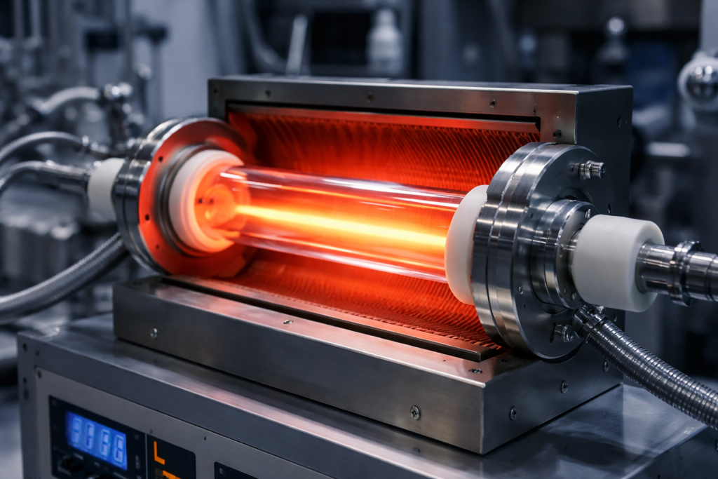
Fused quartz rods are widely used as both finished components and starting materials for precision-machined parts in semiconductor equipment.
At first glance, a quartz rod appears simple:
solid material + round diameter + specified length
But once the rod becomes part of a precision semiconductor assembly, additional requirements quickly become important.
Engineers may need to control:
- Diameter tolerance
- Roundness
- Cylindricity
- Straightness
- Length tolerance
- End-face flatness
- Perpendicularity
- Surface roughness
- Ground or polished finish
- Chamfers and radii
- Holes and slots
- High-temperature dimensional stability
- Material purity
- Metal contamination
- Cleaning and packaging
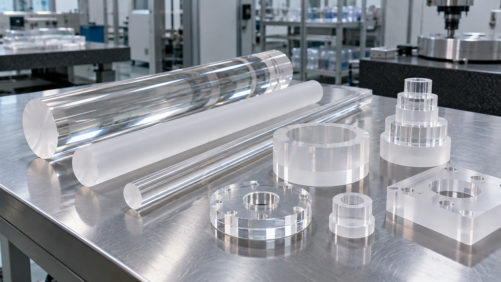
A rod that is suitable as general industrial quartz stock may not be suitable as a positioning pin, furnace support, wafer carrier component or precision semiconductor fixture.
For this reason, custom quartz rod components should be specified as precision engineered parts, not simply by nominal diameter and length.
This article explains the most important considerations when specifying fused quartz rods and solid machined quartz parts for semiconductor equipment.
1. Why Fused Quartz Rods Are Used in Semiconductor Equipment
Fused quartz combines several properties that make it useful around semiconductor process equipment.
These include:
- High chemical purity
- High-temperature stability
- Very low thermal expansion
- Electrical insulation
- Resistance to many process chemicals
- Low contamination potential
- Good dimensional stability
- Compatibility with precision grinding and polishing
High-purity fused quartz rods are commercially used in silicon semiconductor processing and wafer-carrier applications. Different material grades are available depending on the required purity and process environment.
Typical applications can include:
- Wafer carrier components
- Quartz support rods
- Furnace fixtures
- Positioning pins
- Spacer rods
- Insulating shafts
- Probe supports
- Sensor supports
- Quartz plungers
- Guide elements
- Process chamber components
- Plasma-tool components
- Custom CNC-machined quartz parts
The exact shape can range from a simple cylindrical rod to a highly machined component containing flats, steps, holes, slots and polished surfaces.
2. Quartz Rod vs Solid Machined Quartz Part
It is useful to distinguish these two categories.
Fused Quartz Rod
A quartz rod is generally supplied as cylindrical stock.
Typical specifications include:
- Diameter
- Length
- Material grade
- Surface condition
- Straightness
It may be used directly or as raw material for additional fabrication.
Solid Machined Quartz Part
A solid quartz component begins with:
- Rod
- Ingot
- Plate
- Block
- Solid blank
and is then processed into a final geometry.
Machining may include:
- Cutting
- OD grinding
- Surface grinding
- Drilling
- Slotting
- CNC contouring
- Lapping
- Polishing
- Fire finishing
Quartz solids are available specifically as fabrication stock for semiconductor wafer-processing components.
The starting material should therefore be selected according to the finished geometry rather than assuming every part should begin with standard rod stock.
3. Diameter Tolerance Is the First Critical Dimension
For many quartz rod components, diameter is the most important specification.
A drawing should clearly state:
Nominal Diameter + Tolerance
For example:
Ø12.00 ±0.05 mm
rather than:
Approx. 12 mm
The required tolerance depends on how the rod is used.
A quartz rod that simply supports another structure may tolerate relatively large dimensional variation.
A quartz rod that fits into:
- A ceramic bore
- A precision clamp
- A mechanical guide
- A sealing interface
may require tighter control.
Tighter tolerances normally require additional grinding and inspection.
Therefore, the tolerance should be based on function rather than specifying the smallest possible value.
4. As-Formed Diameter vs Precision-Ground Diameter
Standard quartz rod production provides useful dimensional consistency, but precision semiconductor applications may require further finishing.
Two general conditions should be distinguished.
As-Formed Rod
The diameter is determined primarily by the original manufacturing process.
Advantages:
- Lower cost
- Minimal machining
- Suitable for general supports
- Good for subsequent fabrication
Precision-Ground Rod
The OD is mechanically ground to a controlled dimension.
Advantages can include improved:
- Diameter tolerance
- Roundness
- Straightness
- Cylindrical geometry
- Surface consistency
Therefore, an RFQ should state whether the requested diameter is:
raw rod size
or
finished precision-ground diameter
These are not the same product.
5. Diameter Should Be Measured at Multiple Locations
A rod may measure correctly near one end but vary slightly along its length.
For precision components, inspection may need to include measurements at:
- End A
- Center
- End B
or at more locations depending on length.
It may also be useful to measure in multiple rotational directions.
This provides information about both:
- Diameter variation
- Roundness
A statement such as:
Ø20.00 ±0.03 mm over full functional length
is more meaningful than a single diameter measurement at one point.
6. Diameter Tolerance and Roundness Are Different
A component may meet the nominal diameter specification while still being slightly oval.
For example:
Maximum measured diameter:
20.02 mm
Minimum measured diameter:
19.98 mm
The component may still satisfy a ±0.03 mm diameter tolerance.
However, a precision application may also care about the difference between those measurements.
This is where roundness becomes relevant.
Diameter describes:
the size of the cylinder
Roundness describes:
how closely each cross-section approaches a true circle
Applications involving rotation, close fits or sealing may require both.
7. Cylindricity Adds Another Level of Control
Roundness examines individual cross-sections.
Cylindricity considers the entire cylindrical surface.
A rod can be round at several measurement positions but still show:
- Taper
- Barrel shape
- Hourglass shape
- Local diameter variation
For highly precise assemblies, cylindricity can be more useful than a basic diameter tolerance.
However, specifying cylindricity unnecessarily can increase machining and inspection cost.
It should therefore be used where the entire OD acts as a functional surface.
8. Straightness Is Critical for Long Quartz Rods
Straightness becomes increasingly important as the length-to-diameter ratio increases.
Consider:
Ø5 mm × 50 mm
versus
Ø5 mm × 500 mm
Even if both rods have the same diameter tolerance, the longer rod presents a much greater straightness challenge.
A long rod that curves slightly may cause:
- Positioning errors
- Binding
- Poor assembly
- Uneven support
- Interference with neighboring components
For this reason, length should always be considered together with straightness.
9. Straightness Should Be Specified Over a Defined Length
The phrase:
“Rod must be straight.”
is not a measurable engineering specification.
A better drawing may define:
Straightness ≤ X mm over Y mm length
or use an appropriate geometric tolerance.
The allowable value should reflect the actual assembly.
For a simple furnace support, moderate straightness may be sufficient.
For a precision alignment shaft, a significantly tighter requirement may be needed.
10. Straightness and Runout Are Not the Same
These terms are sometimes confused.
Straightness
Evaluates whether the rod’s axis or surface follows a straight line.
Runout
Evaluates variation when the component rotates relative to a defined datum axis.
A rod used in a rotating mechanism may therefore require a runout specification.
A stationary support rod may require only straightness.
The drawing should match the functional requirement.
11. Fused Quartz Is Brittle Despite Its High-Temperature Capability
Quartz performs extremely well in many high-temperature environments, but it should still be treated as a brittle glass material.
Surface flaws are especially important because scratches, chips and grinding damage can reduce mechanical strength.
Momentive notes that fused quartz has high compressive strength but that surface flaws can significantly reduce usable strength.
This has important consequences for machining.
A dimensionally accurate part can still have poor reliability if machining produces:
- Deep scratches
- Edge chips
- Subsurface damage
- Sharp corners
Therefore, dimensional inspection and surface inspection should be performed together.
12. Cutting Fused Quartz Rods
The first machining step is often cutting rod stock to length.
Methods depend on:
- Rod diameter
- Material grade
- Required end finish
- Quantity
After cutting, the end may require:
- Grinding
- Lapping
- Polishing
- Fire polishing
depending on the application.
A rough cut end should not automatically be used as a precision datum.
If the end face controls assembly position, it should receive a defined finishing operation.
13. Why Grinding Is Important
Grinding is one of the most important processes for producing precision quartz parts.
It can be used to control:
- OD
- Length
- Flatness
- Parallelism
- Slots
- Steps
- Complex profiles
Grinding removes material mechanically using abrasive tools.
For semiconductor components, the objective is usually not only material removal but controlled geometry.
A rough grinding stage may establish basic shape.
Subsequent fine grinding can improve:
- Tolerance
- Surface condition
- Geometry
before final polishing or other finishing.
14. OD Grinding for Quartz Rods
Outside-diameter grinding can transform standard rod stock into a more precise cylindrical component.
It can help improve:
- Diameter
- Roundness
- Cylindricity
- Straightness
This is particularly useful for rods used as:
- Precision spacers
- Guide shafts
- Locating components
- Alignment pins
The required stock allowance should be considered before selecting the raw rod.
For example, if the final diameter is:
Ø20.00 mm
it is usually not helpful to begin with raw stock already below that dimension.
Sufficient machining allowance must remain for the grinding operation.
15. Centerless Grinding Can Be Useful for Cylindrical Components
For suitable cylindrical geometry and production volume, centerless-style grinding approaches can provide efficient OD control.
Instead of locating the component between conventional centers, the workpiece is supported and guided during grinding.
Potential advantages can include:
- Consistent diameter
- Good roundness
- Efficient processing of multiple rods
However, not every quartz part is suitable.
Components with:
- Large steps
- Complex ends
- Fragile features
- Non-cylindrical sections
may require a different grinding strategy.
Manufacturing method should be selected according to final geometry.
16. Grinding Leaves a Different Surface From Polishing
A ground quartz surface generally appears:
- Frosted
- Matte
- Diffuse
A polished quartz surface may appear:
- Clear
- Smooth
- Glossy
These are not simply cosmetic differences.
Grinding produces microscopic surface and subsurface damage.
Additional fine grinding, lapping or polishing can reduce surface roughness and remove part of the damaged layer.
Therefore, a specification such as:
OD precision ground
is not equivalent to:
OD polished
The customer should state which surface condition is actually required.
17. When Is a Ground Surface Sufficient?
Not every semiconductor component needs optical polishing.
Ground surfaces may be suitable for:
- Mechanical supports
- Furnace fixtures
- Non-sliding interfaces
- Hidden assembly features
- Non-optical surfaces
In some applications, a controlled ground surface may actually be preferable because it avoids unnecessary polishing cost.
The correct principle is:
polish only where function requires polishing.
18. When Should a Quartz Surface Be Polished?
Polishing may be appropriate when the surface is used for:
- Optical transmission
- Precision sliding contact
- High-cleanliness applications
- Sealing
- Low-particle interfaces
- Inspection windows
- High-quality reference surfaces
A polished cylindrical rod can also be useful where surface defects must be minimized.
However, polishing a full long cylindrical OD can be significantly more demanding than polishing a flat surface.
This should be considered during cost evaluation.
19. Mechanical Polishing vs Fire Polishing
These processes should not be confused.
Mechanical Polishing
Material is progressively removed using controlled abrasives.
It can improve:
- Surface roughness
- Flatness
- Dimensional precision
- Optical quality
Fire Polishing
The quartz surface is locally heated until microscopic surface irregularities soften.
This can produce a smoother appearance.
However, fire polishing can also slightly modify:
- Edge geometry
- Small features
- Local dimensions
Therefore, it is not always suitable for a dimensionally critical ground part.
If diameter tolerance is extremely important, finishing method should be agreed before fabrication.
20. End-Face Flatness
Many rod components are installed between two surfaces.
In this case, end-face flatness can affect mechanical stability.
A poorly finished end may have:
- Saw marks
- Local high points
- Chipped edges
- Convexity
- Concavity
If the end face acts as a datum or support surface, it may need precision grinding or lapping.
This is especially important for:
- Spacers
- Stand-offs
- Vertical supports
- Precision-length rods
21. End-Face Perpendicularity
A rod can have the correct length while still sitting at an angle if the end face is not square to its cylindrical axis.
Perpendicularity becomes important when:
- The rod stands vertically
- Two end faces locate the assembly
- Multiple rods must support a common plate
- Alignment is critical
A drawing should therefore distinguish:
Length tolerance
from
end-face perpendicularity
They control different characteristics.
22. Parallelism Between Two End Faces
For spacer applications, the two end faces may also need to remain parallel.
If one end is tilted relative to the other, the supported assembly may tilt.
When multiple quartz spacers are used together, dimensional matching can become even more important.
Customers may need to specify:
- Individual length tolerance
- Lot matching
- End-face parallelism
rather than simply ordering nominally identical rods.
23. Chamfers Reduce Edge Chipping
Sharp quartz edges are vulnerable to damage.
A controlled chamfer can reduce the risk of:
- Edge chipping
- Handling damage
- Assembly damage
- Particle generation
Common drawing callouts may define:
- Chamfer width
- Chamfer angle
or a small radius.
However, excessive chamfering can interfere with a functional contact surface.
The chamfer should therefore be designed according to the assembly.
24. Machined Flats on Quartz Rods
Some cylindrical quartz components require one or more flat surfaces.
Possible functions include:
- Anti-rotation
- Alignment
- Mechanical locating
- Sensor mounting
- Clamping
A drawing should specify:
- Flat width
- Flat depth
- Flat length
- Location relative to other features
- Surface finish
If two flats are required, their angular relationship may also need control.
25. Steps and Shoulders
A quartz rod can be ground into a stepped shaft.
For example:
Ø20 mm
↓
Ø15 mm
↓
Ø10 mm
Such components may be used for:
- Locating
- Supporting
- Isolating
- Mounting
Important specifications include:
- Diameter of each section
- Step location
- Shoulder perpendicularity
- Transition radius
A perfectly sharp internal corner should generally be avoided where possible because brittle materials are sensitive to stress concentration.
26. Holes in Solid Quartz Components
Solid quartz rods and blocks can also contain:
- Axial holes
- Radial holes
- Blind holes
- Through holes
These features may be used for:
- Gas flow
- Fasteners
- Sensors
- Electrodes
- Assembly alignment
Small holes require careful manufacturing because quartz is brittle.
The combination:
small diameter + deep hole + tight position tolerance
can significantly increase processing difficulty.
If a bore is a critical feature, it should be specified separately from the external rod geometry.
27. Slots and Grooves
Custom quartz components may require:
- Circumferential grooves
- Longitudinal slots
- Wafer-positioning slots
- Retaining features
These can be produced through precision machining when geometry permits.
Important considerations include:
- Slot width
- Depth
- Corner radius
- Position
- Surface finish
Narrow deep slots and sharp internal corners are generally more challenging than open, radiused features.
Design for manufacturability should therefore be considered before the drawing is frozen.
28. Surface Roughness Should Match Function
Surface roughness should not be specified simply because a low Ra value looks impressive on a drawing.
Different surfaces may have different functions.
For example:
| Surface | Possible Requirement |
|---|---|
| General OD | Ground |
| Locating OD | Fine ground |
| Sliding surface | Polished |
| Optical surface | Optical polish |
| End datum | Lapped / polished |
| Noncritical feature | As-machined |
This approach controls cost while maintaining performance.
29. Polishing Cannot Correct Every Geometry Error
A common misunderstanding is that polishing will make an inaccurate component precise.
Polishing primarily improves surface quality.
Major geometric corrections should normally be achieved during:
- Cutting
- Grinding
- Lapping
before final polishing.
If a rod has excessive:
- Diameter variation
- Taper
- Bow
- End-angle error
these issues should be corrected before the final finishing stage.
30. Surface Damage From Grinding Must Be Controlled
Grinding glass can create both visible and subsurface damage.
Fine finishing stages are therefore important when mechanical reliability or surface quality is critical.
Historical fused-silica finishing studies have shown that grinding-induced subsurface flaws can influence strength, reinforcing the importance of controlling the full grinding and finishing sequence rather than considering surface appearance alone.
This is particularly relevant for:
- Thin sections
- High-stress parts
- Thermally cycled components
- Vacuum components
A heavily ground surface should not automatically be assumed to have the same mechanical reliability as a properly finished surface.
31. Thermal Expansion Is Very Low—but Assembly Design Still Matters
Fused quartz has an exceptionally low coefficient of thermal expansion.
Published quartz material data show values around the order of 5 × 10⁻⁷/K, depending on grade and temperature range.
This makes quartz valuable in thermally demanding semiconductor equipment.
However, problems can arise when quartz is rigidly connected to materials with much higher thermal expansion, such as certain metals.
During heating:
metal expands more
while
quartz expands very little
If the assembly does not allow differential movement, mechanical stress can develop.
Therefore, equipment design should consider:
- Flexible mounts
- Clearance
- Spring loading
- Suitable seals
- Controlled clamping
Quartz should not be excessively constrained.
32. High-Temperature Stability Depends on Geometry and Load
Fused quartz is commonly used at elevated temperatures, but maximum operating capability depends on:
- Material grade
- Temperature
- Exposure duration
- Component size
- Applied load
- Support spacing
At high temperatures, quartz gradually becomes less rigid.
A long horizontal quartz rod supporting a heavy component may slowly sag even if it does not fracture.
For this reason, high-temperature design should consider both:
strength
and
long-term deformation
33. Purity Is Part of the Component Specification
Semiconductor-grade quartz parts should not be specified by geometry alone.
Raw material purity can be critical.
Depending on grade, impurities may include trace amounts of:
- Aluminum
- Sodium
- Potassium
- Lithium
- Iron
- Copper
- Calcium
- Titanium
Commercial semiconductor quartz grades range from high-purity natural fused quartz to ultra-high-purity synthetic material. Momentive, for example, lists rod grades from >99.995% SiO₂ to synthetic grades exceeding 99.9999% SiO₂ for highly purity-sensitive applications.
The most expensive material is not automatically necessary for every component.
Material grade should reflect:
- Position relative to wafer
- Process temperature
- Chemistry
- Contamination budget
34. Natural Fused Quartz vs Synthetic Fused Silica
Both can be appropriate for semiconductor components.
High-Purity Natural Fused Quartz
Often suitable for:
- Furnace fixtures
- General semiconductor quartzware
- Support rods
- Wafer-processing components
Synthetic Fused Silica
May be selected when extremely low impurity content or specific optical properties are required.
Synthetic fused silica is available with very low trace-metal levels for contamination-sensitive semiconductor applications.
Using synthetic material for every mechanical support may unnecessarily increase cost.
Conversely, a general industrial-grade rod may be inappropriate near a contamination-sensitive process.
35. Cleaning After Grinding and Polishing
Machining introduces contaminants.
Possible sources include:
- Abrasive particles
- Tool residue
- Grinding slurry
- Handling contamination
- Polishing compounds
A finished semiconductor component may therefore require a controlled cleaning sequence.
Depending on application, this can involve:
- High-purity water
- Chemical cleaning
- Ultrasonic cleaning
- Multiple rinses
- Controlled drying
The cleaning method must be compatible with the required surface condition.
36. Do Not Destroy a Precision Surface During Cleaning
Aggressive chemical treatment can remove a small amount of quartz material.
This may be acceptable for general cleaning but can be relevant when:
- Diameter tolerance is extremely tight
- Optical polish must be preserved
- Small features are present
Cleaning strategy should therefore be considered part of manufacturing rather than something performed without regard to dimensions.
Final critical dimensions may need to be verified after the complete finishing and cleaning process.
37. Clean Packaging Matters
After cleaning, the component should remain protected until installation.
Packaging requirements may include:
- Individual bags
- Double bags
- Cleanroom packaging
- Non-shedding cushioning
- Protected ends
- Part separation
Long polished rods should also be supported adequately to prevent impact during transport.
A component that leaves the factory clean can still generate particles if it rubs against another quartz part during shipping.
38. Inspection of Precision Quartz Rods
A suitable inspection plan may include:
Diameter
Micrometer or appropriate precision measurement.
Roundness
Multiple angular measurements or dedicated roundness equipment.
Straightness
Reference surface or dedicated metrology.
Length
Precision dimensional measurement.
End-Face Flatness
Optical or mechanical methods depending on tolerance.
Perpendicularity
Measured relative to cylindrical datum.
Surface Roughness
Profilometry or optical measurement depending on required finish.
Visual Inspection
For:
- Chips
- Scratches
- Cracks
- Bubbles
- Inclusions
The measurement method should be appropriate for the tolerance being specified.
39. Inspection Datums Should Reflect Final Assembly
Suppose a custom rod has:
- Ground OD
- Flat on one side
- Axial hole
- Precision end face
Which feature should be Datum A?
The answer depends on how the component is mounted.
If the equipment locates the part by OD, then OD may be the correct primary reference.
If an axial bore controls alignment, the bore may be more important.
The drawing should reflect actual equipment function instead of choosing datums only for drawing convenience.
40. Avoid Unnecessary Tight Tolerances
One of the most common mistakes in custom quartz design is specifying:
- Very tight OD
- Very tight straightness
- Very low roughness
- Optical polish
- Tight end-face flatness
on every surface.
This can greatly increase:
- Machining time
- Inspection time
- Reject rate
- Cost
- Lead time
A better approach is to classify dimensions.
Critical
Directly affects equipment function.
Important
Needs good control but not extreme precision.
Noncritical
Can use normal fabrication tolerance.
This produces a more manufacturable and economical design.
41. Selecting Raw Stock for a Machined Quartz Part
Final geometry should determine raw-material selection.
For a simple cylindrical support:
quartz rod stock
may be ideal.
For a large complicated component:
solid quartz ingot or block
may provide better machining allowance.
For a thin ring:
quartz tube or hollow cylinder
may reduce material waste.
The most efficient starting form minimizes:
- Material removal
- Machining time
- Waste
- Risk
Manufacturing cost is therefore influenced by both finished dimensions and raw-material geometry.
42. Example Custom Quartz Rod Specification
A typical RFQ could read:
Product: Precision Fused Quartz Rod
Application: Semiconductor Process Equipment
Material: High-Purity Fused Quartz
Finished Diameter: Ø12.00 ±0.03 mm
Length: 250.00 ±0.10 mm
Straightness: According to drawing
Roundness: According to drawing
Ends: Precision ground
End Perpendicularity: According to drawing
Chamfer: C0.3 × 45°
OD Finish: Fine ground
Cleaning: Semiconductor compatible
Packaging: Individually clean packed
Quantity: 10 pcs prototype / 200 pcs production
This is much clearer than:
“Quartz rod, 12 × 250 mm.”
43. Example Solid Machined Quartz Part RFQ
For a more complex component:
Material: High-Purity Fused Quartz
Starting Form: Rod or Solid Blank
Maximum OD: Ø40 mm
Overall Length: 60 mm
Precision OD: Ø30.00 ±0.03 mm
Step OD: Ø20.00 ±0.03 mm
Axial Hole: Ø6.00 ±0.05 mm
Flat Width: According to drawing
End Flatness: Drawing specified
Perpendicularity: Drawing specified
Surface: Ground, selected surfaces polished
Chamfers: Drawing specified
Cleaning: Semiconductor-grade
Quantity: 5 pcs samples followed by batch order
A 2D drawing or 3D model should be supplied wherever possible.
44. Prototype Before Tightening the Specification
For a new precision quartz component, prototype production is often valuable.
The first batch allows the customer to evaluate:
- Fit
- Straightness
- Surface quality
- Assembly alignment
- Thermal behavior
- Cleaning
- Actual tolerance requirements
Sometimes the initial drawing specifies a much tighter tolerance than the equipment actually needs.
After prototype testing, a tolerance may be relaxed.
In other cases, testing may reveal that one overlooked parameter—such as end perpendicularity—is more important than diameter.
This information can improve both performance and production cost.
45. Questions to Ask a Quartz Machining Supplier
Before placing an order, ask:
- Which fused quartz grade is recommended?
- Will the component start from rod or solid ingot?
- What machining allowance is required?
- How will the OD be ground?
- How will straightness be measured?
- Can roundness or cylindricity be controlled?
- How are end faces finished?
- Can perpendicularity and parallelism be inspected?
- Which surfaces should be polished?
- Can holes, flats or slots be machined?
- How are edge chips controlled?
- What cleaning process is available?
- Can semiconductor-grade packaging be provided?
- Can dimensional inspection records be supplied?
- Which drawing tolerance is most difficult to manufacture?
- Can the design be modified to improve yield?
These questions are more useful than comparing diameter and unit price alone.
46. Design for Manufacturability
The best custom quartz parts are usually designed through cooperation between:
equipment engineer + quartz fabricator
Small design changes can sometimes significantly improve manufacturability.
Examples include:
- Adding a small internal radius
- Relaxing a noncritical tolerance
- Increasing minimum wall thickness
- Reducing unnecessary polishing area
- Changing raw stock size
- Increasing hole diameter slightly
- Moving a hole away from an edge
These modifications can reduce breakage and cost without affecting equipment performance.
47. Grinding and Polishing Should Be Treated as Different Engineering Steps
A useful way to think about the process is:
Raw Quartz
↓
Cutting
↓
Rough Machining
↓
Precision Grinding
↓
Fine Grinding / Lapping
↓
Polishing Where Required
↓
Cleaning
↓
Final Inspection
Each step has a different purpose.
Grinding establishes geometry.
Lapping improves precision and surface condition.
Polishing improves the final surface.
Cleaning removes process contamination.
Inspection confirms whether the complete part—not simply the raw material—meets the drawing.
Conclusion
Fused quartz rods and solid machined quartz components used in semiconductor equipment should be specified as precision parts rather than generic glass stock.
The most important parameters often include:
diameter tolerance + roundness + straightness + cylindricity + end geometry + surface finish + purity + cleanliness
A correct diameter does not guarantee a straight rod.
A straight rod does not guarantee roundness.
A ground surface does not provide the same finish as a polished surface.
And a perfectly polished part can still fail if the geometry, material purity or cleaning process is inappropriate for the semiconductor environment.
For simple components, standard high-purity quartz rod stock may provide an economical starting point.
For demanding equipment, additional processes such as:
- OD grinding
- Precision surface grinding
- Drilling
- Slotting
- Lapping
- Polishing
allow the material to be converted into custom semiconductor components.
When preparing an RFQ, engineers should identify which surfaces and dimensions actually control equipment performance.
A complete drawing should define:
material grade, finished dimensions, tolerances, straightness, roundness, end-face requirements, surface finish, machining features, cleaning and packaging.
This allows the quartz manufacturer to choose the most suitable raw material and machining route while balancing precision, reliability, cost and production yield.