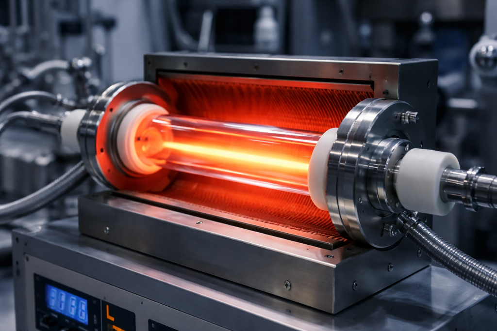
In semiconductor equipment, a quartz tube is not always simply a hollow component used to carry gas or withstand high temperature.
For many precision assemblies, the internal bore itself is a functional mechanical feature.
The bore may be required to:
- Guide a ceramic rod
- Position a sensor
- Carry process gas
- Align an optical component
- Hold an electrode
- Support a thermocouple
- Interface with another precision tube
- Maintain a controlled annular gap
- Provide a chemically clean flow path
In these applications, standard fused quartz tubing may not provide sufficient dimensional control.
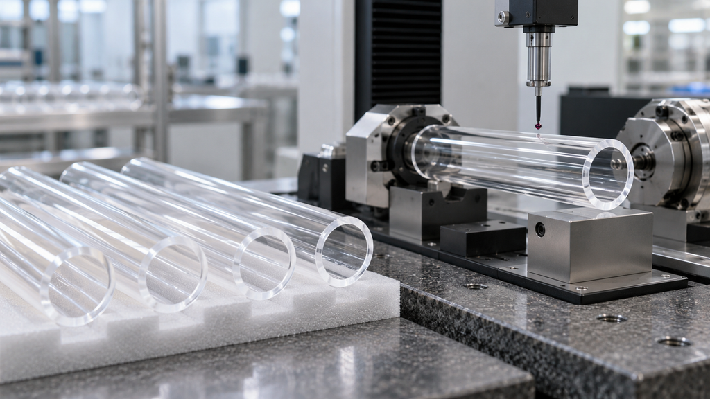
The engineering discussion therefore shifts from simply specifying:
OD × wall thickness × length
to defining a much more complete set of parameters:
ID tolerance + bore roundness + concentricity + straightness + surface finish + end geometry + cleanliness
This article explains how engineers should specify precision-bore fused quartz tubes for semiconductor and high-precision equipment.
1. What Is a Precision-Bore Fused Quartz Tube?
A precision-bore fused quartz tube is a tubular quartz component in which the internal hole is manufactured or selected to meet tighter dimensional and geometric requirements than ordinary commercial tubing.
Depending on the design, the component may be produced from:
- Drawn fused quartz tubing
- Thick-wall quartz tubing
- Redrawn tubing
- Quartz rod with a machined axial bore
- Near-net-shape quartz blanks
- Synthetic fused silica material
The optimum manufacturing route depends strongly on:
- Inner diameter
- Outer diameter
- Wall thickness
- Overall length
- ID tolerance
- Concentricity requirement
- Bore straightness
- Surface finish
- Production quantity
For example, a long thin-wall tube with a moderate ID tolerance may be manufactured differently from a short, thick-wall component with a small precision axial bore.
The term precision bore therefore describes a dimensional requirement rather than one single manufacturing method.
2. Why Standard Quartz Tubing May Not Be Precise Enough
Standard fused quartz tubing is suitable for many furnace, laboratory and process applications.
However, normal tube manufacturing inevitably produces some variation in:
- ID
- OD
- Wall thickness
- Ovality
- Straightness
- Concentricity
For a simple furnace liner, these variations may be completely acceptable.
For a semiconductor positioning component, they may not be.
Consider a quartz tube used to guide a precision ceramic shaft.
If the nominal ID is correct but the bore varies along its length, the shaft may:
- Bind at one location
- Become loose at another location
- Tilt relative to the system axis
- Contact the quartz wall during motion
Similarly, a tube used for controlled gas flow may produce an inconsistent annular gap if the inner bore is not sufficiently centered.
The correct question is therefore not:
“Can you supply a quartz tube with ID 10 mm?”
It is:
“What functional tolerance does the 10 mm bore need to maintain across the required length?”
3. ID Tolerance: The First Critical Specification
The inner diameter is normally the most important dimension in a precision-bore component.
A drawing should always state both:
Nominal ID
and
Allowable tolerance
For example:
ID: Ø10.00 mm ±0.05 mm
is much clearer than:
Approx. 10 mm ID
But tolerance should be determined by function.
A tighter tolerance is not automatically better.
Extremely tight tolerances can increase:
- Processing time
- Inspection requirements
- Scrap rate
- Manufacturing cost
- Lead time
The target tolerance should therefore be based on the actual assembly requirement.
4. Clearance Must Be Designed Into the Bore
Suppose a quartz tube must accept a ceramic shaft.
If the shaft OD is:
Ø9.90 ±0.02 mm
and the quartz bore is specified as:
Ø10.00 ±0.02 mm
the minimum possible clearance becomes very small.
This may create assembly problems when other factors are considered:
- Bore straightness
- Shaft straightness
- Particle contamination
- Thermal expansion
- Alignment error
- Surface roughness
For sliding or removable assemblies, engineers should evaluate the complete tolerance stack rather than comparing nominal dimensions alone.
A functional bore often needs controlled clearance, not simply the smallest possible dimensional tolerance.
5. ID Tolerance and Bore Roundness Are Not the Same
A tube may meet the specified inner diameter and still not have a perfectly circular bore.
For example, measurements taken in two directions may show:
- Horizontal ID: 10.02 mm
- Vertical ID: 9.96 mm
The nominal bore may still appear close to 10 mm, but its cross-section is slightly oval.
This is why precision designs may need a separate requirement for:
Bore roundness or ovality
ID tolerance answers:
How large is the bore?
Roundness answers:
How circular is the bore?
For alignment, sealing and controlled-clearance applications, both may matter.
6. Concentricity: Is the Bore Actually Centered?
Concentricity describes the relationship between the internal bore and the external cylindrical geometry.
A tube can have an accurate ID and OD but still have the bore positioned off-center.
Conceptually:
Good concentricity
OD center ≈ ID center
Poor concentricity
OD center ≠ ID center
Poor concentricity creates unequal wall thickness around the circumference.
This can matter when the quartz component is located mechanically from its outside diameter while another component is positioned by the internal bore.
Examples include:
- Precision gas-delivery assemblies
- Electrode supports
- Sensor tubes
- Optical alignment assemblies
- Ceramic rod guides
- Semiconductor furnace components
If OD and ID axes are not sufficiently aligned, the internal component will also be displaced from the equipment centerline.
7. Wall-Thickness Uniformity and Concentricity Are Related
For a perfectly concentric tube:
Wall thickness is approximately uniform around the circumference.
When the bore moves away from the OD centerline:
- One side becomes thicker
- The opposite side becomes thinner
Therefore, measuring wall thickness around the tube can help evaluate bore location.
However, wall-thickness variation can result from several factors, including:
- Bore eccentricity
- OD ovality
- ID ovality
- Grinding variation
- Tube-forming variation
For demanding assemblies, concentricity should be specified and inspected directly according to the functional datum defined on the drawing.
8. Bore Straightness Is Critical for Long Tubes
A precision bore can have the correct diameter at both ends and still curve slightly through the component.
This is particularly important for long quartz parts.
Imagine looking through a long tube:
At the inlet, the bore appears centered.
At the outlet, it also appears centered.
But between the two ends, the bore centerline may deviate.
This can create problems when inserting:
- Long ceramic rods
- Optical fibers
- Electrodes
- Thermocouples
- Gas injectors
- Alignment pins
For these components, engineers should consider specifying:
Bore straightness
in addition to ID and concentricity.
9. Tube Straightness and Bore Straightness Are Different
This distinction is important.
Tube Straightness
Describes how straight the external body of the tube is.
Bore Straightness
Describes how closely the internal bore follows its intended axis.
A tube can appear externally straight while the internal bore drifts.
Likewise, the internal bore may be relatively straight but not fully concentric with the OD.
For precision semiconductor components, drawings should define exactly which geometry is functionally critical.
10. Surface Finish Inside the Bore
Dimensional accuracy alone may not be sufficient.
The internal surface condition can affect:
- Particle generation
- Gas flow
- Cleaning
- Chemical adsorption
- Component insertion
- Sliding friction
- Optical performance
- Contamination retention
The required finish depends heavily on the application.
Possible conditions include:
- As-formed
- Ground
- Fine ground
- Lapped
- Polished
- Fire-finished
- Application-specific internal finish
A bore used simply to route gas does not necessarily require the same finish as a bore used to guide a precision mechanical element.
11. Why an Overly Rough Bore Can Be a Problem
A rough internal surface can contain microscopic peaks, valleys and machining marks.
Possible consequences include:
Particle Retention
Contaminants may become trapped more easily in irregular surface features.
Difficult Cleaning
Cleaning solutions may not remove embedded particles as effectively.
Increased Friction
Inserted ceramic or quartz components may drag against the wall.
Particle Generation
Mechanical contact can release small particles from either the tube or inserted component.
Flow Effects
For certain small-bore gas or liquid systems, surface condition may influence local flow behavior.
Therefore, the functional surface requirement should be discussed before manufacturing.
12. But a Mirror Finish Is Not Always Necessary
It is equally important not to over-specify.
Requiring an optically polished bore when the component only transports process gas may add significant manufacturing cost without improving equipment performance.
Surface finish should therefore be divided into categories:
Mechanical Bore
Designed primarily for dimensional fit.
Clean-Flow Bore
Designed for gas or liquid transport with contamination control.
Precision Guide Bore
Designed to locate or guide another component.
Optical Bore
Designed for optical transmission or alignment.
Each category may justify a different machining and polishing strategy.
13. Surface Roughness Should Include the Measurement Method
If a numerical roughness requirement is important, the drawing should define more than a single Ra value.
Engineers should consider specifying:
- Ra or RMS
- Measurement direction
- Measurement length
- Instrument type
- Measurement location
A roughness result measured on the outer surface cannot automatically be assumed to represent the internal bore.
Small internal diameters can also make direct bore measurement much more difficult.
Therefore, the inspection method should be agreed during the design stage.
14. Precision Bore Manufacturing Methods
Different geometries require different manufacturing routes.
There is no universal process suitable for every quartz tube.
Possible routes include:
Precision Tube Selection
For moderately tight requirements, a manufacturer may select suitable tubes from controlled production batches.
This is often more economical than extensive machining.
Redrawing
Quartz tubing can sometimes be thermally resized to achieve smaller or more controlled geometry.
This approach may be useful for certain long, small-diameter tubes.
Bore Grinding
Mechanical grinding can enlarge or correct an internal bore.
This is useful when accurate diameter control is required.
Lapping
Lapping can improve:
- Dimensional consistency
- Geometry
- Surface finish
especially for rigid short components.
Drilling From Solid Quartz
For thick-wall components with relatively small central bores, starting from a solid quartz rod may be more appropriate.
The bore can then be drilled and subsequently finished.
Combined ID and OD Machining
When tight concentricity is required, both the internal bore and external diameter may need to be processed relative to controlled datums.
This is often more effective than trying to hold a highly precise bore inside an uncontrolled outer surface.
15. Why Thick-Wall Quartz Parts Can Be Better for Precision Bores
A standard thin-wall tube is not always the ideal starting material.
For a precision component such as:
OD 25 mm / ID 3 mm / length 50 mm
the structure is closer to a quartz cylinder with an axial hole than a conventional tube.
A thick-wall blank can provide additional material for:
- OD grinding
- Bore correction
- Concentricity adjustment
- End-face grinding
This can make it easier to establish accurate geometric datums.
However, the most appropriate starting material still depends on final dimensions and quantity.
16. Long Small Bores Are Particularly Difficult
A combination such as:
small ID + long length + tight tolerance
is significantly more challenging than the same bore in a short component.
This is because tool access, straightness and inspection all become more difficult as the aspect ratio increases.
For example:
A Ø2 mm through-hole in a 10 mm long quartz component is a very different manufacturing problem from a Ø2 mm bore through a 300 mm component.
When sending an RFQ, engineers should therefore always provide:
ID + total bore length
rather than ID alone.
17. Aspect Ratio Should Be Considered Early
A useful conceptual parameter is:
Bore Aspect Ratio = Bore Length / Bore Diameter
As the ratio increases, manufacturers may face greater difficulty maintaining:
- Straightness
- Diameter consistency
- Surface finish
- Tool stability
- Inspection access
High-aspect-ratio bores should therefore be discussed with the manufacturer before the drawing is finalized.
Sometimes a slight increase in bore diameter or reduction in required length can significantly improve manufacturability.
18. End Faces Matter More Than Many Drawings Show
A precision-bore tube is often integrated into another mechanical assembly.
The two tube ends may therefore act as datum surfaces.
Important specifications can include:
- Length
- End-face flatness
- End-face perpendicularity
- Parallelism
- Chamfer
- Edge radius
If one end face is not square to the bore axis, the component may tilt when installed against a mechanical stop.
This can negate the benefit of a highly accurate internal bore.
19. Perpendicularity Between Bore and End Face
Consider a tube mounted vertically on a flat plate.
Even if the bore is perfectly straight, an angled bottom face can make the entire component lean.
For positioning applications, engineers may therefore define:
End face perpendicular to bore axis
rather than simply:
End face polished
These are different requirements.
“Polished” describes surface condition.
“Perpendicular” describes geometry.
20. Chamfers and Edge Breaks
Freshly machined fused quartz edges can be vulnerable to chipping.
A controlled chamfer or edge radius can improve:
- Handling
- Assembly
- Cleaning
- Packaging
- Installation durability
Typical drawings may specify:
C0.2
or another drawing-specific chamfer.
However, very small components or thin walls may require different edge treatment.
Chamfer size should therefore be selected according to available wall thickness and functional geometry.
21. Fire Polishing Versus Mechanical Finishing
Fire polishing can smooth sharp or frosted quartz surfaces by controlled thermal treatment.
It can be useful for certain edges and surfaces.
However, it should not automatically be used on every precision-bore component.
Thermal finishing may influence:
- Local dimensions
- Edge shape
- Small-hole geometry
- Surface condition
For a dimensionally critical bore, aggressive fire treatment near the opening may change the exact edge geometry.
Therefore:
dimensional requirement should be defined before cosmetic surface requirement.
22. Cleaning Precision-Bore Quartz Components
After machining, the component may contain:
- Grinding residue
- Quartz particles
- Handling contamination
- Cleaning chemistry residue
For semiconductor equipment, final cleaning can be as important as machining.
A small internal bore is particularly difficult because particles can remain trapped inside the channel.
Cleaning may therefore require a combination of:
- Ultrasonic cleaning
- High-purity water rinsing
- Chemical cleaning
- Controlled drying
- Cleanroom packaging
The exact process should depend on the customer’s cleanliness requirements and the compatibility of the final application.
23. Bore Protection During Packaging
A precision bore should remain clean after final inspection.
Packaging design may include:
- Protected tube openings
- Double bagging
- Clean polyethylene packaging
- Caps that do not shed particles
- Individual part separation
- Shock-resistant outer packaging
A finished bore should not be exposed unnecessarily after cleaning.
For very small holes, preventing packaging particles from entering the bore is especially important.
24. How to Inspect the Inner Diameter
Inspection method depends on the size and tolerance.
Possible tools include:
Plug Gauges
Useful for certain functional bore sizes.
A go/no-go gauge can quickly verify whether a bore is within the required functional range.
Precision Internal Gauges
Can provide quantitative ID measurements where tool access allows.
Optical Measurement
Useful for end geometry and some smaller holes.
Coordinate Measurement
May be used for accessible precision geometries.
Bore Scanning or Specialized Metrology
May be required when diameter variation along the full bore is critical.
For a long precision tube, measuring only the two ends may not be sufficient.
25. Inspection Locations Must Be Defined
Suppose the drawing states:
ID 8.00 ±0.03 mm
Where should that dimension be measured?
Possible options include:
- At both ends
- At the center
- At three axial locations
- At multiple indexed cross-sections
- Over the entire functional length
For tight specifications, the inspection plan should define measurement locations.
Otherwise, the customer and manufacturer may interpret the same drawing differently.
26. Measuring Concentricity
For a precision-bore quartz component, inspection typically needs a clearly defined datum system.
For example:
Datum A: External cylindrical surface
Datum B: Bottom face
The bore position can then be evaluated relative to these datums.
For another application, the bore itself may be the primary functional datum and the OD may be machined relative to it.
This difference matters.
The drawing should reflect how the part is actually located in the final equipment.
27. Do Not Specify OD, ID and Wall Thickness Independently Without Checking the Stack
For a simple ideal tube:
Wall thickness = (OD − ID) / 2
Therefore, OD, ID and wall thickness are mathematically linked.
If a drawing independently assigns very tight tolerances to all three, the combination may become difficult or contradictory.
A better approach is to determine which dimensions are functionally critical.
For example:
Application A
Critical:
- ID
- Concentricity
Less critical:
- Exact OD
Application B
Critical:
- OD
- Wall thickness
Less critical:
- Exact ID
Application C
Critical:
- OD
- ID
- Concentricity
This will generally require a more precision-intensive manufacturing route.
28. Common Applications in Semiconductor Equipment
Precision-bore quartz components may be used in:
Gas Delivery
Controlled internal passages for process gases.
Furnace Equipment
Quartz supports, injectors and internal process structures.
Wafer Processing Equipment
Precision positioning or isolation components.
Plasma Processing
High-purity dielectric structures in chemically aggressive environments.
Sensor Housings
Protection and alignment of temperature or optical sensors.
Electrode Supports
Insulating support around conductive components.
Optical Systems
Alignment or protection of optical elements.
Analytical Instruments
Controlled sample or gas pathways.
The exact quartz grade and geometry should always be selected based on the actual process environment.
29. Natural Fused Quartz vs Synthetic Fused Silica
Material selection should also be discussed when the application is sensitive to purity or optical transmission.
Possible material families include:
- Natural fused quartz
- High-purity fused quartz
- Synthetic fused silica
The optimum choice depends on:
- Semiconductor contamination requirements
- OH content
- UV transmission
- IR performance
- Thermal environment
- Budget
There is no reason to specify synthetic fused silica for every mechanically machined precision tube if the application does not require its specific material characteristics.
Conversely, a general industrial quartz grade may not be appropriate for a contamination-sensitive semiconductor process.
30. Avoid Over-Specifying the Component
One of the most common causes of unnecessary quartz machining cost is excessive specification.
For example, a drawing may request:
- Extremely tight ID tolerance
- Extremely tight OD tolerance
- Very low roughness
- Tight concentricity
- Tight straightness
- Optical polish
- Very small chamfer tolerance
even though only one or two parameters affect actual equipment performance.
Each additional requirement may reduce manufacturing yield.
The best engineering approach is:
tight tolerance where function requires it, practical tolerance everywhere else.
31. A Better Way to Prepare the Drawing
A useful precision-bore quartz drawing should identify critical dimensions rather than treating every dimension equally.
For example:
Critical Characteristics
ID: Ø8.00 ±0.03 mm
Concentricity: Drawing specified
Bore straightness: Drawing specified
Functional length: 120 mm
Secondary Characteristics
OD: Ø15.0 ±0.1 mm
Overall length: 125 ±0.2 mm
End Requirements
Ground end faces
Specified chamfer
No visible edge chips within acceptance limit
Surface
Internal finish as specified
External finish as required
Cleanliness
Semiconductor-process cleaning requirement
This is much easier to manufacture and inspect than a drawing filled with unexplained tolerance values.
32. Recommended RFQ Information
When requesting a custom precision-bore fused quartz tube, provide at least:
| Parameter | Required Information |
|---|---|
| Material | Fused quartz / fused silica grade |
| OD | Nominal + tolerance |
| ID | Nominal + tolerance |
| Length | Nominal + tolerance |
| Wall thickness | If functionally critical |
| Bore length | Through bore or blind bore |
| Concentricity | Required value if critical |
| Bore straightness | Required if applicable |
| Roundness | Required if applicable |
| Tube straightness | Required if applicable |
| Internal finish | Ground / lapped / polished / other |
| External finish | As required |
| End-face finish | Cut / ground / polished |
| Perpendicularity | If required |
| Parallelism | If required |
| Chamfer | Size and angle |
| Cleaning | Industrial / high-purity / semiconductor |
| Packaging | Standard / clean packed |
| Quantity | Prototype / sample / batch |
| Application | Semiconductor, optical, furnace, etc. |
33. Example Precision-Bore Quartz Tube RFQ
A useful inquiry might read:
Product: Precision-Bore Fused Quartz Tube
Material: High-Purity Fused Quartz
OD: Ø20.00 mm ±0.05 mm
ID: Ø6.00 mm ±0.02 mm
Length: 80.00 mm ±0.10 mm
Bore: Through hole
Concentricity: According to attached drawing
Bore Straightness: Critical
End Faces: Precision ground
Chamfer: Drawing specified
Internal Surface: Fine finished
Cleaning: Semiconductor compatible
Quantity: 5 pcs prototype, followed by 100 pcs production
Application: Semiconductor equipment
Providing a drawing is strongly recommended.
If the assembly is particularly sensitive, customers should also indicate which feature is the primary datum.
34. Prototype Before Production
For very tight precision-bore components, prototype qualification is often more practical than moving directly into volume production.
A prototype batch allows both sides to evaluate:
- Dimensional capability
- Inspection method
- Assembly clearance
- Surface finish
- Cleanliness
- Packaging
- Actual equipment performance
After prototype testing, tolerances can sometimes be relaxed or adjusted before production.
This may reduce cost while improving manufacturing stability.
35. What to Ask a Precision Quartz Manufacturer
Before ordering, engineers can ask:
- What starting material will be used?
- Will the bore be formed, drilled, ground or lapped?
- How will the ID be measured?
- At how many positions will the ID be checked?
- How will concentricity be measured?
- Can bore straightness be inspected?
- Can the internal surface be polished if required?
- How are end faces referenced to the bore?
- Can OD grinding be performed after bore machining?
- What cleaning process is available?
- How will the bore be protected after cleaning?
- Can inspection records be supplied?
- Is prototype production available?
- Which tolerance is most difficult on the drawing?
- Can the design be optimized for manufacturability?
These questions usually provide more useful information than simply asking for the lowest unit price.
Conclusion
Precision-bore fused quartz tubes for semiconductor equipment should be treated as precision engineered components, not ordinary glass tubing.
The key parameters are interconnected:
ID tolerance + roundness + concentricity + straightness + surface finish + end geometry + cleanliness
A correct inner diameter does not guarantee a centered bore.
A centered bore does not guarantee bore straightness.
A tight dimensional tolerance does not guarantee a clean or smooth internal surface.
And an extremely precise component can still fail in the equipment if assembly clearance and datum relationships are not properly designed.
For this reason, the best results come from defining the functional requirements first.
Engineers should identify:
- What passes through the bore
- Which surface locates the component
- What clearance is required
- Which dimensions are truly critical
- How the component will be inspected
- What level of cleanliness is required
Once these conditions are clear, the manufacturing route can be selected around the application rather than forcing the application to fit a standard quartz tube.
For custom semiconductor quartz components, a detailed drawing showing OD, ID, bore length, tolerance, concentricity, straightness, end-face requirements and cleaning specifications is the most effective starting point for technical evaluation and quotation.