Custom quartz components are frequently used in semiconductor processing equipment, laboratory systems, vacuum assemblies, high-temperature furnaces and optical instruments. These components may include quartz tubes, flanges, chambers, boats, carriers, rings, windows, nozzles and welded assemblies.
Because many quartz parts are custom-made, dimensional inspection cannot be limited to checking only the overall length and outer diameter. A component may meet its basic dimensions but still fail during installation because of incorrect hole positions, poor flange flatness, excessive concentricity error, an unsuitable sealing surface or leakage from a welded joint.
A reliable inspection plan should therefore combine dimensional measurement, visual examination, leak testing and traceable documentation.
This guide explains how coordinate measuring machines, optical measurement systems, profile instruments and leak-testing equipment can be used to verify custom quartz components before shipment.
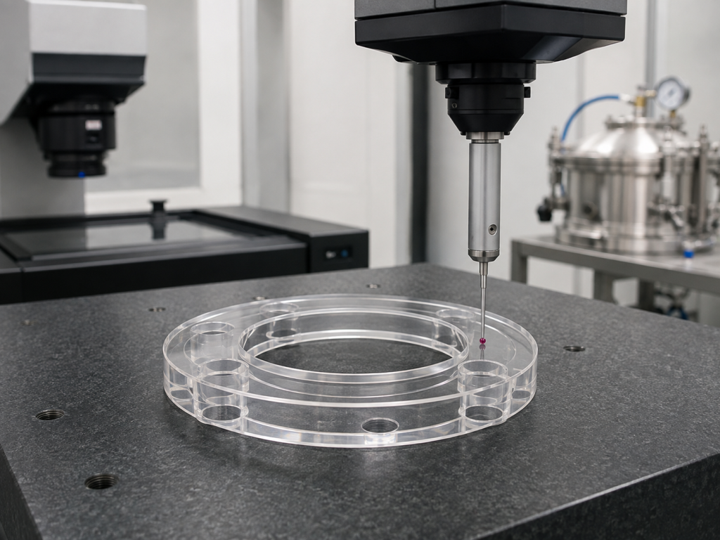
Why Quartz Component Inspection Requires a Defined Plan
Quartz components often contain a combination of simple and complex features:
- Outer and inner diameters
- Wall thickness
- Overall length and height
- Bolt-hole diameter and position
- Slot width and pitch
- Flange thickness
- Sealing-face flatness
- Parallelism
- Perpendicularity
- Concentricity
- Port angle and orientation
- Weld position
- Internal depth
- Surface roughness
- Leak integrity
These characteristics cannot always be verified accurately with one measuring instrument.
A vernier caliper may be suitable for a non-critical external dimension, but it is usually insufficient for verifying a bolt-hole pattern or a tight positional tolerance. A contact CMM can measure many three-dimensional features, but it may not be the best method for a very thin quartz wall, a polished optical surface or a small transparent feature.
The inspection method should be selected according to:
- The component geometry
- The tolerance level
- The surface condition
- The risk of measurement damage
- The required measurement uncertainty
- The customer’s reporting requirements
ISO 1101 provides the standardized symbol language used to define geometrical characteristics such as form, orientation, location and run-out on engineering drawings. Clear geometrical tolerancing makes it easier for the buyer and supplier to agree on exactly what must be measured.
1. Converting the Drawing into an Inspection Plan
Inspection should begin before manufacturing rather than after the component has been completed.
The supplier should review the drawing and divide the dimensions into several groups.
Critical-to-Function Dimensions
These dimensions directly affect installation, sealing, alignment or equipment operation.
Examples include:
- Flange outer and inner diameter
- Sealing-face flatness
- Bolt-circle diameter
- Hole position
- Port orientation
- Chamber concentricity
- Slot pitch
- Mating dimensions
- Quartz-to-metal interface dimensions
Critical dimensions commonly require tighter control, more capable equipment and more complete reporting.
General Dimensions
These dimensions are necessary for part definition but may not directly control system performance.
Examples include:
- Non-mating overall length
- Non-critical wall thickness
- External support dimensions
- Unspecified corner radii
- Cosmetic transitions
These dimensions may be checked using calipers, micrometers, height gauges, templates or optical systems, depending on the tolerance.
Reference Dimensions
Reference dimensions are normally included for information and should not automatically be treated as acceptance requirements.
The drawing should clearly distinguish between:
- Toleranced dimensions
- Reference dimensions
- Basic dimensions
- Theoretical coordinates
- Inspection-only dimensions
Without this distinction, the supplier may inspect the wrong characteristic or produce a report that does not reflect the actual functional requirement.
2. CMM Inspection of Quartz Components
A coordinate measuring machine, or CMM, creates a three-dimensional coordinate system and measures points on a component using a tactile or non-contact sensor.
CMM inspection is particularly useful when the component contains multiple features that must be related to common datums.
Quartz Features Commonly Measured by CMM
A CMM can be used to inspect:
- Hole diameter
- Hole-to-hole distance
- Bolt-circle diameter
- Port location
- Port angle
- Plane flatness
- Parallelism
- Perpendicularity
- Concentricity
- Coaxiality
- Cylinder diameter
- Slot position
- Profile deviation
- Overall three-dimensional geometry
For example, a quartz flange may have the correct outer diameter and hole diameters but still fail assembly if the holes are positioned incorrectly relative to the flange center. A CMM can establish the flange axis, sealing plane and hole coordinates within one measurement program.
ISO 10360-2 specifies acceptance and reverification testing for CMM performance when measuring linear dimensions. The purpose is to verify that the measuring system continues to perform within its stated capability.
Tactile CMM Measurement
A tactile CMM uses a probe stylus that physically contacts the component.
It is suitable for relatively stable quartz features such as:
- Thick flanges
- Large external diameters
- Accessible bores
- Rigid welded assemblies
- Ground surfaces
- Datum planes
- Bolt holes
However, probing force and fixturing pressure must be controlled.
Thin quartz tubes, narrow lips, polished surfaces and delicate edges may be damaged or deflected by inappropriate contact measurement. Non-contact sensors are used in industrial metrology specifically to inspect delicate components without applying measurement pressure.
CMM Fixturing Requirements
A quartz component must be supported without introducing stress or deformation.
An unsuitable fixture may create false measurement results by:
- Bending a thin tube
- Tilting a flange
- Distorting a large ring
- Loading a welded joint
- Covering a critical feature
- Allowing movement during probing
A good fixture should:
- Locate the component repeatably
- Use minimum clamping force
- Support the part near stable structural areas
- Avoid contact with polished surfaces
- Provide access to critical features
- Use soft, clean and non-contaminating contact materials
The inspection report should identify the datum system and, when necessary, the measurement orientation.
Datum Selection
CMM results depend strongly on how the coordinate system is established.
A quartz flange assembly might use:
- Datum A: sealing face
- Datum B: central bore axis
- Datum C: one specified bolt hole or orientation feature
This datum structure allows the supplier to measure hole positions, port orientation and perpendicularity relative to the actual assembly interface.
The supplier should not create an inspection datum that conflicts with the drawing or the way the part is installed in the customer’s equipment.
3. Optical Measurement for Transparent Quartz Parts
Optical measurement is often highly suitable for quartz because it does not require physical contact.
Vision measuring machines use cameras, lenses, controlled illumination and image-processing software to detect edges and calculate dimensions. These systems can inspect small, flat, thin or delicate components without probe contact.
Features Suitable for Optical Measurement
Optical systems can be used for:
- Small hole diameter
- Slot width
- Slot pitch
- Edge profile
- Wafer outline
- Flat quartz plate dimensions
- Thin ring dimensions
- Notch geometry
- Chamfer width
- Surface defect size
- Printed or laser-marked reference features
- Two-dimensional contour comparison
Transmitted lighting is often useful for measuring the silhouette of a transparent or thin component. Ring, coaxial and top lighting can be selected to highlight different surfaces and edges. Optical measurement accuracy depends heavily on illumination, focus, threshold settings and edge-detection strategy.
Challenges When Measuring Transparent Quartz
Transparent components may produce reflections from multiple surfaces. A measuring system may detect:
- The front surface
- The back surface
- An internal reflection
- A bevel transition
- A polished edge
- A coating interface
This can cause unstable edge detection if the measurement program and lighting are not properly configured.
Some chromatic optical sensors can distinguish the upper and lower surfaces of transparent materials and measure both position and thickness. This capability can be useful for quartz windows, transparent plates and thin substrates.
The customer and supplier should agree on:
- Measurement side
- Edge-detection method
- Illumination mode
- Focus strategy
- Surface or interface being measured
- Treatment of bevels and rounded edges
- Magnification
- Calibration method
Optical CMM and Multisensor Inspection
A multisensor system may combine:
- Camera measurement
- Chromatic white-light measurement
- Laser scanning
- Touch-trigger probing
- Rotary-axis measurement
This allows one inspection program to measure both two-dimensional and three-dimensional features.
For example, an optical camera may measure a quartz flange’s bolt-hole pattern, while a tactile probe measures an internal bore and a chromatic sensor scans the sealing surface.
ISO 10360-8 specifies performance verification for Cartesian CMMs using optical distance sensors. The standard was reviewed and confirmed in 2024, meaning the published edition remains applicable.
4. Profile, Flatness and Surface Measurement
Some quartz characteristics cannot be represented adequately by only a few coordinate points.
Flatness Measurement
Flange and window flatness may be evaluated by:
- CMM point measurement
- Optical flat and interference fringes
- Laser measurement
- White-light interferometry
- Surface profilometry
- Dedicated flatness gauge
The selected method depends on:
- Component size
- Transparency
- Surface finish
- Required tolerance
- Whether the surface is polished or ground
- Whether the inspection is local or full-area
A small number of CMM points may miss a localized high or low area. When sealing performance depends on the entire surface, a denser scan or full-field optical method may be more appropriate.
Surface Profile and Step Height
White-light interferometry and chromatic sensors can measure three-dimensional surface topography without contact. Such systems are used for surface analysis, depth measurement and small-feature height measurement.
Possible quartz applications include:
- Recess depth
- Raised sealing ring height
- Step height
- Local flatness
- Surface waviness
- Polished-area transition
- Etched feature depth
- Coating thickness difference
ISO 25178 provides a framework for areal surface texture measurement, including method classification, parameters and calibration or verification of surface-topography instruments.
Surface Roughness
Surface roughness may be measured using:
- Contact stylus profilometer
- White-light interferometer
- Confocal optical system
- Atomic force microscope for very fine surfaces
The report should state the actual parameter, such as Ra, Rq or Sa, rather than only stating “smooth surface.”
It should also identify:
- Cutoff length
- Evaluation length
- Filter
- Measurement direction
- Number of measurement locations
- Instrument type
- Surface preparation condition
A roughness result without measurement conditions may not be reproducible between the supplier and customer.
5. Leak Testing of Quartz Components
Leak testing is necessary when a quartz component forms part of a:
- Vacuum chamber
- Gas delivery system
- Furnace tube assembly
- Process chamber
- Sealed reactor
- Quartz manifold
- Welded flange assembly
- Fluid-handling system
Leak testing verifies system integrity by creating a pressure difference and detecting gas or liquid movement through an unintended opening. The selected method depends on required sensitivity, component size, operating conditions and access to the internal volume.
Visual and Bubble Leak Testing
Bubble testing is a relatively simple method for locating gross leaks.
The component is pressurized with a suitable gas, and either:
- The part is immersed in liquid, or
- Leak-detection solution is applied to joints and surfaces
The appearance of bubbles indicates a leakage location.
Bubble testing is useful for:
- Initial weld-process checks
- Large visible leaks
- Low-cost screening
- Locating a known pressure loss
- Non-critical utility components
However, it should not be selected when the required acceptance limit is below the reliable sensitivity of the method.
Pressure Decay Testing
Pressure decay testing involves pressurizing a sealed component and monitoring the pressure over a defined period.
A pressure reduction may indicate leakage, but results can also be affected by:
- Temperature change
- Internal volume
- Fixture leakage
- Gas stabilization
- Component deformation
- Instrument resolution
- Test duration
The test procedure should define:
- Test gas
- Test pressure
- Stabilization time
- Measurement time
- Allowable pressure change
- Component volume
- Ambient temperature range
- Fixture verification
- Instrument calibration
Pressure-decay testing can be useful for production screening, but the customer should not assume that pressure loss can be converted directly into a precise leak rate unless the system has been properly characterized.
Vacuum Decay Testing
Vacuum decay testing evacuates the component and monitors pressure rise.
It is suitable for components designed to operate under vacuum, but fixture outgassing, trapped moisture and temperature effects must be considered.
Helium Mass-Spectrometer Leak Testing
Helium leak testing is used when higher sensitivity and a quantitative leak rate are required.
Common test arrangements include:
- Vacuum method
- Helium spray method
- Sniffer method
- Pressurized helium method
- Chamber accumulation method
Helium is widely used as a tracer because it can be detected at very low concentrations using a mass spectrometer. ASNT identifies mass-spectrometer testing as one of the most sensitive commonly used industrial leak-testing techniques.
For semiconductor-related gas components, SEMI F1 defines leak-testing requirements and leakage-rate limits for high-purity gas piping systems and components. It covers complete systems, subsystems and individual components and is intended to support procurement and installation.
Quartz Weld Inspection
A quartz weld may appear visually acceptable but still contain:
- A fine through-leak
- An incomplete fusion area
- A local crack
- A thin wall
- Excessive deformation
- Residual contamination
- A stress-sensitive transition
Leak testing should therefore be performed after the final welding, annealing and cleaning processes when leak integrity is a critical requirement.
The test fixture itself should be checked before the part is evaluated. Otherwise, leakage from an O-ring, blanking plate, hose or adapter may be incorrectly attributed to the quartz component.
Defining a Leak-Test Requirement
Avoid specifications such as:
- No leakage
- Fully airtight
- Vacuum tight
- Good sealing
- No bubbles
A measurable requirement should state:
- Test method
- Tracer gas or test fluid
- Test pressure or vacuum level
- Acceptance leak rate
- Test direction
- Stabilization time
- Test duration
- Test temperature
- Fixture configuration
- Calibration requirement
- Report format
There is no single universal leak-rate limit for all quartz components. The correct value depends on the process gas, operating pressure, vacuum level, component volume and consequences of leakage.
6. Visual Inspection and Defect Documentation
Dimensional conformity does not guarantee acceptable quartz quality.
Visual inspection may identify:
- Chips
- Cracks
- Scratches
- Inclusions
- Bubbles
- Weld marks
- Contamination
- Burn marks
- Devitrification
- Edge damage
- Surface stains
- Residue inside tubes or chambers
The inspection specification should define:
- Lighting condition
- Background
- Viewing distance
- Magnification
- Inspection area
- Defect type
- Maximum defect size
- Maximum defect quantity
- Restricted functional zones
- Cosmetic zones
For complex components, photographs or a defect map can be more useful than a general statement such as “visual inspection passed.”
7. Sampling Inspection or 100% Inspection
Not every dimension must be measured on every component.
A practical control plan may use:
100% Inspection
Suitable for:
- Critical mating dimensions
- Sealing surfaces
- Leak integrity
- High-value welded assemblies
- Safety-related dimensions
- Small production quantities
- Custom one-off components
- Characteristics with a history of variation
Sampling Inspection
Suitable for:
- Stable production processes
- Repetitive batch production
- General dimensions
- Non-critical visual characteristics
- Dimensions controlled by validated tooling
The sampling plan should define:
- Lot size
- Sample size
- Acceptance number
- Rejection number
- Inspection level
- Treatment of failed lots
- Reinspection rules
- Record-retention requirements
When a customer requires a particular sampling standard or acceptable quality level, it should be stated in the purchase order rather than assumed.
8. Measurement Uncertainty and Acceptance Decisions
A measured value should not be treated as perfectly exact.
Every measurement contains uncertainty associated with factors such as:
- Instrument performance
- Calibration uncertainty
- Operator technique
- Fixturing
- Temperature
- Measurement strategy
- Surface condition
- Probe selection
- Optical threshold
- Data fitting
- Part repeatability
This becomes particularly important when a result is close to the tolerance limit.
ISO 14253-1 establishes decision rules for verifying conformity or nonconformity while taking measurement uncertainty into account. It specifically addresses situations in which a measured value lies close to a specification limit.
For tight-tolerance quartz components, the buyer and supplier should agree on:
- Applicable decision rule
- Guard band, when used
- Maximum acceptable measurement uncertainty
- Method for resolving disputed results
- Whether uncertainty is included on the report
ISO 14253-3 provides guidance for reaching agreement when customers and suppliers dispute measurement-uncertainty statements.
9. Calibration and Measurement Traceability
Inspection equipment should be calibrated or verified at appropriate intervals.
ISO/IEC 17025 is the international standard addressing the competence of testing and calibration laboratories. It supports confidence in laboratory methods, technical competence and the validity of measurement results.
An inspection system may include:
- Calibrated CMM
- Calibrated micrometers and calipers
- Certified gauge blocks
- Calibrated optical scale
- Reference sphere
- Certified surface standard
- Calibrated pressure transducer
- Calibrated helium leak standard
- Temperature and humidity monitoring
The inspection report does not necessarily need to contain every calibration certificate. However, the supplier should be able to provide equipment identification and calibration status when required.
10. What Should Be Included in a Quartz Inspection Report?
A useful inspection report should allow the customer to match the results to the drawing and the delivered component.
Basic Identification
The report should include:
- Customer name
- Purchase order number
- Part name
- Drawing number
- Drawing revision
- Supplier part number
- Batch or lot number
- Component serial number
- Quantity inspected
- Inspection date
Dimensional Results
For each reported characteristic, include:
- Dimension number
- Nominal value
- Upper tolerance
- Lower tolerance
- Measured result
- Inspection method
- Pass or fail status
For geometrical characteristics, the report should also identify the datum reference system.
Equipment Information
Depending on customer requirements, include:
- Equipment type
- Equipment identification number
- Calibration due date
- Software version
- Probe or sensor type
- Measurement program number
Leak-Test Results
A leak-test section should include:
- Test method
- Test gas
- Test pressure
- Test duration
- Acceptance limit
- Measured leak rate or pressure change
- Equipment identification
- Test fixture identification
- Pass or fail result
Supporting Documents
Supporting documentation may include:
- CMM graphical report
- Hole-position diagram
- Surface profile plot
- Flatness map
- Leak-test printout
- Defect photographs
- Material certificate
- Cleaning certificate
- Packaging inspection record
Approval
The report should identify:
- Inspector
- Reviewer or quality approval
- Report revision
- Date of approval
- Any deviations or concessions
A report that only states “all dimensions passed” provides limited traceability and may not be sufficient for critical semiconductor-equipment components.
11. Example Inspection Plan for a Custom Quartz Flange Assembly
A typical inspection plan may be organized as follows:
| Characteristic | Requirement | Method | Frequency |
|---|---|---|---|
| Overall height | Drawing tolerance | Height gauge or CMM | 100% |
| Flange outer diameter | Drawing tolerance | CMM or optical system | 100% |
| Central bore | Drawing tolerance | CMM | 100% |
| Bolt-hole diameter | Drawing tolerance | Optical system or CMM | 100% |
| Bolt-hole position | True-position requirement | CMM | 100% |
| Sealing-face flatness | Drawing requirement | CMM scan or optical method | 100% |
| Port angle | Drawing requirement | CMM | 100% |
| Port length | Drawing tolerance | CMM or optical system | 100% |
| Weld appearance | Approved visual criteria | Controlled visual inspection | 100% |
| Edge chipping | Approved defect limit | Microscope | 100% |
| Leak integrity | Defined leak-rate limit | Helium or pressure-decay test | 100% |
| Surface cleanliness | Approved standard | Visual and cleaning record | 100% |
| Material | Specified quartz grade | Material certificate | Per batch |
The actual method should be adjusted according to component geometry, tolerance and application.
12. Common Inspection Mistakes
Using a Caliper for Tight Positional Tolerances
A caliper may measure hole size but usually cannot reliably verify a true-position requirement relative to multiple datums.
Measuring Transparent Edges Without Defining the Detected Surface
The instrument may measure a front reflection, rear reflection or bevel instead of the intended edge.
Applying Excessive Fixture Force
Tight clamping can distort thin quartz components or create measurement stress.
Reporting Nominal Values Instead of Actual Results
An inspection report should contain measured values when numerical reporting is required.
Omitting Drawing Revision
A correct report against an obsolete drawing may still result in rejection.
Using an Undefined Leak Test
“Vacuum tested” is incomplete without pressure, method, duration and acceptance limit.
Ignoring Measurement Uncertainty
A measurement result located at the exact tolerance boundary may require a defined conformity decision rule.
Inspecting Before Final Processing
Final welding, annealing, cleaning and packaging can affect dimensions, surface condition or leak integrity. Critical final inspection should be performed at the correct production stage.
Quartz Component RFQ Checklist
When requesting a custom quartz component, provide:
- Material grade
- Fully dimensioned drawing
- Drawing revision
- Datum system
- General tolerances
- Critical dimensions
- Geometrical tolerances
- Surface roughness
- Visual defect limits
- Weld requirements
- Leak-test method
- Leak-rate acceptance limit
- Test pressure
- Inspection frequency
- Required report format
- Calibration or traceability requirements
- Serial-number requirements
- Packaging and cleanliness requirements
The more clearly the inspection requirements are defined at the RFQ stage, the lower the risk of disagreement after production.
Conclusion
Quartz component inspection should combine the correct measurement technology with clearly defined acceptance criteria.
CMM inspection is effective for three-dimensional relationships, hole positions, datums and geometrical tolerances. Optical measurement is valuable for thin, delicate, transparent or finely detailed components. Surface-profile systems can evaluate height, flatness and local topography. Leak testing verifies welded joints and sealed assemblies.
A complete quality plan should define:
- What must be measured
- Which instrument will be used
- How the component will be fixtured
- Which datum system applies
- How measurement uncertainty is handled
- Whether inspection is sampled or 100%
- Which leak-test method is required
- What information must appear in the inspection report
This approach allows the quartz supplier and equipment manufacturer to evaluate the component using the same technical criteria and reduces the risk of installation problems, leakage, rework and production delays.
Frequently Asked Questions
Can every quartz component be measured with a CMM?
No. A tactile CMM is suitable for many rigid three-dimensional components, but delicate walls, polished surfaces and transparent microfeatures may be better measured with non-contact optical sensors.
Is optical measurement more accurate than CMM inspection?
Not automatically. Accuracy depends on the equipment, calibration, feature geometry, surface condition, lighting, measurement strategy and required tolerance. The correct method should be selected for each characteristic.
Is bubble testing sufficient for a semiconductor quartz component?
Bubble testing can locate relatively large leaks, but it may not provide the sensitivity required for high-vacuum or high-purity gas applications. Helium mass-spectrometer testing may be required when a quantitative low leak-rate limit is specified.
Should every dimension appear in the inspection report?
Not necessarily. Critical and customer-designated dimensions should normally be reported. General dimensions may be controlled by sampling or process inspection unless the purchase order requires a full dimensional report.
What is the difference between an inspection report and a calibration certificate?
An inspection report records the measured results for the quartz component. A calibration certificate documents the performance and traceability of the measuring equipment or reference standard.
When should leak testing be performed?
For welded quartz assemblies, final leak testing should normally be performed after welding, annealing and final processing that could affect joint integrity.