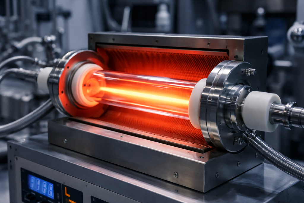
Extreme ultraviolet lithography receives much of the attention surrounding advanced semiconductor manufacturing, but 193nm deep-ultraviolet lithography remains essential for producing logic, DRAM, 3D NAND, power devices and many mature-node products.
Modern semiconductor devices contain many patterned layers. Only the most critical layers may require EUV, while numerous other layers continue to use ArF immersion, dry ArF, KrF or i-line systems. ASML describes its ArF immersion platforms as industry workhorses and continues to develop them for advanced logic and memory manufacturing.
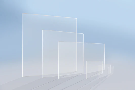
The performance of a 193nm optical system depends partly on the quality of its transmissive materials. Conventional optical glass absorbs strongly at this wavelength, making specially manufactured synthetic fused silica one of the principal materials for ArF optical components.
However, “UV-grade fused silica” does not automatically mean that the material is suitable for high-duty-cycle 193nm lithography. Transmission, refractive-index homogeneity, stress birefringence, laser-induced compaction, fluorescence, inclusions and coating durability must all be evaluated under actual operating conditions.
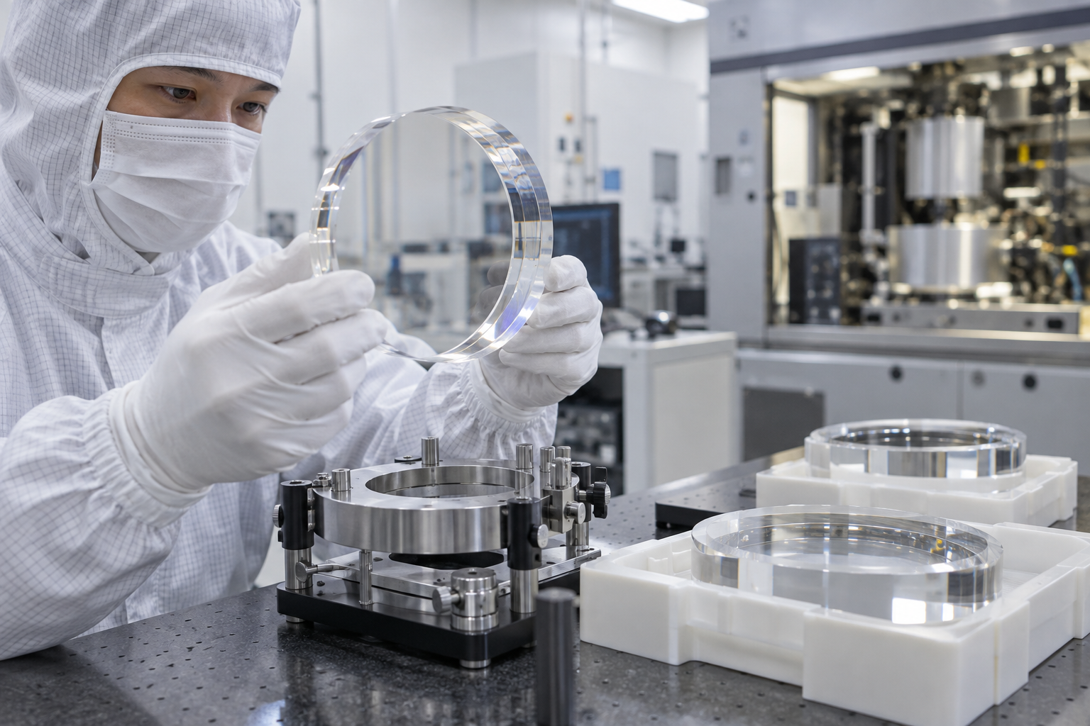
What Is ArF Lithography?
ArF lithography uses an argon-fluoride excimer laser that emits light at approximately 193nm. The shorter wavelength provides higher patterning resolution than 248nm KrF lithography.
ArF systems are divided into two main categories.
Dry ArF lithography
In a dry system, the space between the final projection lens and the wafer is filled with air or another controlled gas. Dry ArF systems are widely used for semiconductor layers that do not require the maximum resolution of immersion technology.
ArF immersion lithography
An immersion system introduces highly purified water between the final lens element and the wafer. The higher refractive index of water increases the numerical aperture and improves resolution.
For example, ASML’s NXT:2050i uses a 1.35 NA, 193nm catadioptric projection lens for high-volume 300mm wafer production. ASML NXT:2050i specifications
Immersion operation places additional demands on optical materials and coatings, including resistance to moisture, contamination, polarization effects and prolonged high-energy exposure.
Why Ordinary Fused Silica May Not Be Suitable
A standard fused silica window can appear perfectly transparent to the human eye while showing unacceptable absorption, fluorescence or refractive-index variation at 193nm.
ArF optical components may experience billions of laser pulses during their service life. Even extremely small changes in material density or refractive index can gradually alter wavefront quality.
An ArF-grade material must therefore control:
- Absorption at 193nm
- Internal scattering
- Metallic impurities
- Hydroxyl content
- Chlorine and other residual species
- Oxygen-deficient defects
- Refractive-index variation
- Residual stress
- Bubbles and inclusions
- Laser-induced compaction
- Polarization-induced changes
The required performance depends on whether the material will be used for a projection lens element, illumination optic, beam-delivery component, inspection window, sensor cover or laser-processing component.
Internal Transmission vs External Transmission
Transmission data must be interpreted carefully.
Internal transmission
Internal transmission describes the light passing through the bulk material after excluding reflection losses from the front and rear surfaces. It is useful for evaluating absorption within fused silica.
External transmission
External transmission includes both bulk absorption and surface reflection. An uncoated fused silica component loses part of the incident light at each air-to-glass interface.
A material can have excellent internal transmission but lower measured external transmission because of surface reflection or coating performance.
The reported transmission value should always identify:
- Test wavelength
- Sample thickness
- Internal or external transmission
- Surface finish
- Coated or uncoated condition
- Measurement temperature
- Measurement uncertainty
A percentage without these conditions is not sufficient for comparing ArF materials.
Why Thickness Matters
Absorption accumulates along the optical path. A transmission result measured through a thin witness sample cannot be directly applied to a thick lens blank without calculation.
For optical systems containing many elements, small absorption differences can accumulate. Excessive absorption may reduce optical power, increase local heating and contribute to wavefront distortion.
Material suppliers may report internal transmission per centimeter or provide an absorption coefficient. Optical designers can then estimate the effect of the actual component thickness.
Refractive-Index Homogeneity
Refractive-index homogeneity describes how consistently light travels through different regions of a fused silica blank.
If the refractive index varies across the clear aperture, different portions of the wavefront experience different optical path lengths. This produces wavefront error that cannot always be removed through surface polishing.
For ArF lithography, index variation may influence:
- Critical-dimension uniformity
- Imaging contrast
- Focus control
- Lens matching
- Aberration correction
- Overlay performance
- Polarization behavior
High-end ArF materials may require index variation controlled to only a few parts per million or less, depending on blank size and optical function.
Corning, for example, lists several homogeneity grades for its HPFS 8650 ArF material, with maximum relative index variations ranging from 0.5ppm to 5ppm. These values are product-specific and should not be treated as a universal industry specification. Corning HPFS 8650 ArF material
How Homogeneity Is Measured
Refractive-index homogeneity is commonly evaluated by interferometry. The measurement may be performed at a visible reference wavelength, such as 632.8nm, even when the finished component will operate at 193nm.
The certificate should explain:
- Measurement wavelength
- Clear-aperture diameter
- Blank thickness
- Test geometry
- Whether the full aperture was measured
- Whether the result is radial, axial or three-dimensional
- Whether surface contributions were subtracted
- Maximum and peak-to-valley index variation
A value measured through the thickness of a parent blank may not completely describe the homogeneity of every finished component cut from it.
Material orientation and cutting position should therefore be controlled for critical optics.
Stress Birefringence
Fused silica is amorphous and does not have the intrinsic crystallographic birefringence found in materials such as sapphire. It can nevertheless become birefringent when mechanical or thermal stress creates direction-dependent refractive-index changes.
Sources of residual stress include:
- Nonuniform consolidation
- Inadequate annealing
- Aggressive grinding
- Subsurface machining damage
- Coating stress
- Mechanical clamping
- Temperature gradients
- Local laser heating
Stress birefringence changes the polarization state of light passing through the component. This is important because modern lithography systems use carefully controlled polarized illumination.
Uncontrolled polarization changes can reduce imaging contrast and create orientation-dependent patterning effects.
Specifying Birefringence
Stress birefringence is often reported as optical retardation per unit thickness, such as nanometers per centimeter. The acceptable value depends on component thickness, optical path and polarization sensitivity.
When reviewing a certificate, confirm:
- Measurement wavelength
- Maximum retardation
- Average retardation
- Measurement direction
- Clear aperture
- Edge exclusion
- Annealing condition
- Whether the value applies to the raw blank or finished optic
The coating and mechanical mount can add stress after the fused silica blank has been certified. Final-component verification may therefore be required.
What Is Laser-Induced Compaction?
Repeated 193nm laser exposure can cause microscopic structural changes in fused silica. One important effect is laser-induced compaction, in which the glass network becomes slightly denser.
Although the dimensional change is extremely small, compaction changes both the physical dimensions and refractive index of the material. Over a long optical path, these changes may create measurable wavefront distortion.
Laser compaction depends on:
- Pulse energy
- Pulse duration
- Repetition rate
- Total accumulated pulse count
- Energy density
- Material composition
- OH concentration
- Manufacturing process
- Defect population
- Operating temperature
A simple laser-damage-threshold value does not describe long-term compaction behavior.
Compaction Is Different From Catastrophic Laser Damage
Laser damage threshold generally refers to the energy level at which visible or irreversible damage occurs, such as pitting, cracking, coating failure or plasma formation.
Compaction can occur at energy densities far below catastrophic damage levels. It is an accumulated material change rather than an immediate failure.
An optic may therefore show no visible damage while its wavefront performance gradually moves outside specification.
ArF material qualification should distinguish between:
- Single-pulse damage
- Multiple-pulse damage
- Long-term compaction
- Laser-induced absorption
- Laser-induced fluorescence
- Polarization-induced birefringence
Compaction and Expansion Behavior
Different fused silica compositions may respond differently to prolonged ArF exposure. Some can show compaction, while others may exhibit competing expansion mechanisms under particular exposure conditions.
Material manufacturers adjust composition and manufacturing parameters to make this behavior smaller and more predictable.
Corning describes its HPFS 8650 as a low-compaction material with minimized polarization-induced birefringence and no measurable expansion under the stated test conditions. This claim applies to that particular grade and exposure method, not to fused silica in general.
When comparing materials, laser-resistance data should be collected under comparable fluence, pulse duration and accumulated dose.
The Role of OH Content
OH content is frequently used when classifying fused silica, but it should not be treated as the only indicator of ArF performance.
Hydroxyl concentration can influence:
- UV defect chemistry
- Infrared absorption
- Viscosity
- Structural relaxation
- Fluorescence
- Laser-induced absorption
- Compaction behavior
Some high-OH synthetic fused silica grades provide excellent DUV transmission and radiation resistance. Other applications may require different OH levels to balance optical and thermal performance.
The relationship between OH and laser durability also depends on chlorine content, oxygen deficiency, hydrogen treatment and the glass manufacturing route.
A procurement specification that states only “high-OH fused silica” or “low-OH fused silica” is incomplete.
Trace Metals and Defect Centers
Metallic impurities may absorb UV energy or contribute to fluorescence and color-center formation. Even very small concentrations can matter in a high-fluence optical system.
Relevant contaminants may include:
- Iron
- Titanium
- Aluminum
- Sodium
- Potassium
- Lithium
- Copper
- Chromium
- Nickel
Chemical purity should be evaluated together with UV transmission and laser-aging data. An extremely low metal concentration does not guarantee acceptable performance if structural defects or residual chemical species remain in the glass network.
Bubbles, Inclusions and Striae
Internal defects may scatter light or distort the transmitted wavefront.
Bubbles
Gas bubbles can scatter the ArF beam and create localized energy concentration. Bubble specifications should include maximum size, permitted quantity and clear-aperture requirements.
Solid inclusions
Foreign particles or unmelted material can absorb laser energy and become damage-initiation sites.
Striae
Striae are localized refractive-index variations caused by composition or thermal-history differences. They may be difficult to detect through visual inspection but can degrade wavefront quality.
High-quality ArF blanks require both low inclusion levels and controlled index homogeneity.
Surface Quality and Subsurface Damage
Bulk material quality alone cannot ensure ArF performance. Grinding and polishing may introduce microcracks, residual stress, embedded particles or a damaged subsurface layer.
At 193nm, surface contamination and microscopic defects can increase scattering, absorption and coating failure risk.
Important finishing requirements include:
- Surface figure
- Surface roughness
- Scratch-dig quality
- Edge quality
- Subsurface damage depth
- Cleaning method
- Particle control
- Metallic surface contamination
The appropriate surface roughness depends on the optical system. Critical projection optics may require substantially more demanding finishes than protective windows or beam-path covers.
Why Coating Requirements Are Different at 193nm
Uncoated fused silica reflects part of the incident light at each interface. In a multi-element optical system, accumulated reflection losses would be unacceptable, so antireflection coatings are commonly applied.
At 193nm, coating materials must provide low absorption in the DUV region. The number of suitable materials is more limited than for visible or near-infrared optics.
An ArF coating must control:
- Reflectance at 193nm
- Absorption
- Laser damage resistance
- Film stress
- Moisture resistance
- Contamination resistance
- Adhesion to fused silica
- Spectral stability
- Polarization behavior
- Uniformity across the clear aperture
Coating performance should be specified for the actual angle of incidence and polarization state. A coating designed for normal incidence may not provide the required behavior at an oblique angle.
Coating Stress and Wavefront Distortion
A deposited coating can place the fused silica substrate under compressive or tensile stress. On thin or highly precise components, this stress may alter surface figure or increase birefringence.
The effect becomes more significant when:
- The substrate is thin
- The coated area is large
- Coating thickness is nonuniform
- The design uses many layers
- Only one side is coated
- The optic operates across a temperature range
Surface figure and birefringence should ideally be verified after coating rather than assumed from the uncoated blank.
Coatings for Immersion Environments
Optics close to the immersion region must tolerate high-purity water and repeated exposure cycles. Moisture can alter some DUV coating materials, especially if pinholes, porosity or edge defects are present.
Qualification may include:
- Soak testing
- Repeated wet-and-dry cycling
- Adhesion testing
- Spectral testing before and after exposure
- Particle inspection
- Surface-energy evaluation
- Contamination testing
Coating durability must be considered together with the fluid-handling and cleaning processes used by the equipment.
Cleaning and Packaging
Organic residue that is harmless in a visible-light system can absorb strongly under DUV exposure. Hydrocarbons may photochemically decompose and form deposits on optical surfaces.
ArF optical components therefore require carefully controlled:
- Polishing compounds
- Cleaning chemicals
- Rinse-water quality
- Drying method
- Handling materials
- Cleanroom environment
- Packaging materials
- Storage conditions
Packaging should protect the polished and coated surfaces without introducing plasticizers, fibers, particles or volatile organic compounds.
ArF Fused Silica Procurement Checklist
A complete request for quotation should specify:
- Application and position in the optical system
- Operating wavelength and bandwidth
- Dry or immersion environment
- Blank diameter, thickness and geometry
- Internal transmission at 193nm
- Refractive-index homogeneity
- Stress-birefringence limit
- Bubble and inclusion class
- Striae requirements
- OH concentration or approved material grade
- Trace-metal limits
- Laser fluence and pulse duration
- Repetition rate and accumulated exposure
- Allowable compaction or wavefront change
- Surface figure and roughness
- Scratch-dig specification
- Subsurface damage requirements
- Coating reflectance and absorption
- Angle of incidence and polarization
- Cleaning and packaging standard
- Required inspection reports and traceability
These parameters should be prioritized according to the actual function of the component. Projection optics, illumination optics and protective windows do not necessarily require the same material grade.
Common Selection Mistakes
Specifying only “JGS1”
JGS1 is a broad commercial designation and does not establish long-term performance under high-duty-cycle 193nm exposure.
Comparing transmission without sample thickness
Transmission percentages measured through different thicknesses cannot be directly compared.
Using visible-light inspection as the primary quality test
A visually clear blank may still contain DUV absorption, fluorescence or index variation.
Ignoring accumulated laser dose
Passing a short laser test does not prove long-term stability over billions of pulses.
Certifying the blank but not the finished optic
Machining, polishing, coating and mounting can change stress and wavefront performance.
Selecting the lowest-OH material automatically
OH content is only one part of ArF material performance and must be considered with the complete defect chemistry.
Conclusion
ArF-grade fused silica is a highly engineered optical material rather than ordinary transparent quartz glass.
For 193nm DUV lithography, high transmission must be combined with excellent refractive-index homogeneity, low stress birefringence, controlled inclusions and predictable behavior under long-term laser exposure.
Laser-induced compaction is especially important because it can gradually change the optical path without producing visible damage. Coatings introduce another layer of risk through absorption, stress, moisture sensitivity and surface contamination.
Reliable material selection therefore requires qualification under defined wavelength, fluence, pulse duration, accumulated dose, polarization and environmental conditions.
The correct ArF fused silica grade is not simply the material with the highest nominal purity. It is the material whose bulk properties, laser-aging behavior, polishing quality and coating performance remain stable throughout the intended service life.