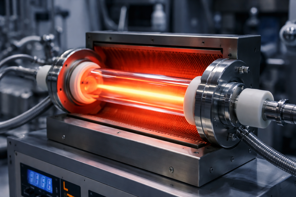
A semiconductor quartz chamber liner is more than a protective sleeve inside process equipment. Its material purity, geometry, surface condition and thermal behavior can directly affect chamber stability, contamination levels, maintenance intervals and wafer yield.
Quartz liners may be used in thermal processing, deposition, oxidation, annealing, UV treatment, vacuum systems and selected plasma-related equipment. Depending on the chamber design, the liner may isolate the process environment from the metal chamber wall, control gas exposure, protect other components or reduce cross-contamination.
One patented semiconductor chamber design, for example, uses a cylindrical quartz liner to separate the process environment from the surrounding chamber wall while controlling purge-gas flow. This illustrates why liner geometry and installation clearances must be designed as part of the complete process system rather than as an independent quartz tube.
For buyers and equipment engineers, specifying only the liner’s diameter, length and nominal purity is not enough. A reliable RFQ should also define the process chemistry, operating temperature, surface finish, particle-control requirement, cleaning grade and inspection method.
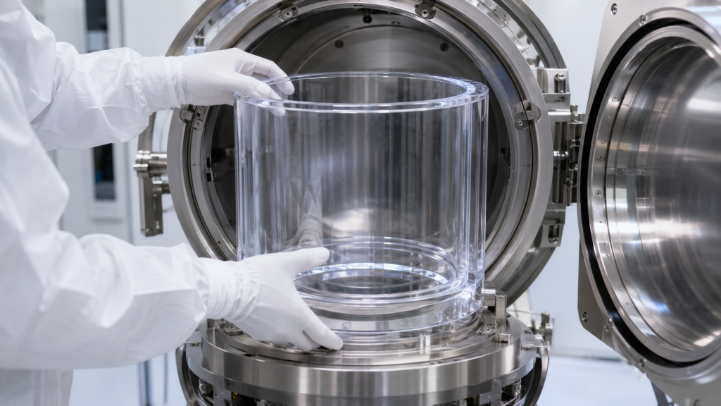
What Does a Quartz Chamber Liner Do?
The exact function depends on the equipment, but common purposes include:
- Isolating process gases from metal chamber walls
- Reducing contact between reactive species and the chamber body
- Protecting the chamber from deposits or chemical attack
- Providing a clean internal process surface
- Limiting metal contamination
- Supporting purge-gas or exhaust-flow control
- Simplifying maintenance and replacement
- Protecting optical or thermal components
- Reducing process memory between different recipes
- Providing electrical insulation
- Transmitting radiant or UV energy where required
The liner may be cylindrical, conical, segmented, slotted, domed or integrated with quartz rings, plates, ports or gas-distribution components.
Its design must match the actual function. A liner for a high-temperature oxidation chamber will not have the same requirements as a liner exposed to fluorine-containing plasma, repeated film deposition or aggressive chamber-cleaning cycles.
1. Material Purity: Start with the Process Risk
“High-purity quartz” is not a complete material specification.
Different fused quartz grades may contain different concentrations of aluminum, sodium, potassium, lithium, iron, calcium, titanium and other trace elements. They may also have different hydroxyl content, bubble levels, viscosity and thermal behavior.
Published fused-quartz material data demonstrates that trace-element and OH levels vary substantially between grades. The material must therefore be selected from measured data rather than from a general marketing description.
Bulk Purity and Surface Cleanliness Are Different
Bulk purity describes the composition of the quartz material itself. Surface cleanliness describes contaminants introduced during cutting, grinding, welding, polishing, handling, cleaning and packaging.
A liner made from high-purity quartz can still introduce contamination if its surface carries:
- Grinding residue
- Polishing compound
- Metal transferred from tools
- Fingerprints
- Alkali contamination
- Cleaning-agent residue
- Packaging particles
- Organic contamination
- Deposited material from previous service
For critical applications, the specification should address both material composition and final surface condition.
Which Elements Should Be Controlled?
The relevant elements depend on the wafer process and contamination budget. Commonly reviewed elements include:
- Sodium
- Potassium
- Lithium
- Iron
- Aluminum
- Calcium
- Magnesium
- Copper
- Nickel
- Chromium
- Titanium
- Boron
- Phosphorus
The RFQ should state whether the supplier must provide a standard material certificate, a full trace-element report or testing for selected critical elements.
Avoid requesting an arbitrary purity percentage without defining the test method and required elements. A total SiO₂ value alone may not reveal the concentration of the contaminant that is most important to the process.
Natural Fused Quartz or Synthetic Fused Silica?
Natural fused quartz is commonly used for many semiconductor thermal components because it can offer good purity, high-temperature stability and relatively low OH content.
Synthetic fused silica can provide extremely low metallic contamination and excellent optical performance, but some grades have different OH levels and viscosity characteristics.
Material selection should consider:
- Maximum temperature
- Process duration
- Thermal-cycle frequency
- Plasma or chemical exposure
- Optical transmission requirements
- Metallic contamination limits
- OH-content limits
- Required mechanical stability
- Cost and component size
There is no single quartz grade that is best for every chamber liner.
2. Geometry and Mechanical Design
A chamber liner must fit the equipment correctly while allowing for installation tolerances, thermal movement, gas flow and maintenance access.
Important drawing parameters include:
- Inner diameter
- Outer diameter
- Wall thickness
- Overall length
- الاستدارة
- Cylindricity
- Straightness
- التراكز
- End-face perpendicularity
- Slot or opening position
- Port diameter and angle
- Flange dimensions
- Support features
- Assembly clearance
- Edge radius or chamfer
- Flatness of sealing or mounting surfaces
Keep Wall-Thickness Transitions Gradual
Abrupt changes in wall thickness heat and cool at different rates. These transitions can produce localized thermal stress, especially near welded rings, support feet, ports and reinforced sections.
Where possible, use smooth transitions and generous radii rather than sharp internal corners.
Avoid Sharp Edges
Sharp edges are vulnerable to chipping during cleaning, installation and thermal cycling. Small chips can become particle sources or initiate larger cracks.
Edges should be chamfered, rounded, ground or fire-finished according to the application.
Control Contact Points
The liner should not be tightly trapped between metal components. Metal and quartz have very different thermal expansion behavior, so an assembly that fits at room temperature may apply excessive stress at process temperature.
The design should define:
- Radial clearance
- Axial clearance
- Support locations
- Clamp force
- Cushioning or isolation method
- Maximum allowable movement
- Installation orientation
Contact points should be stable enough to prevent vibration but should not create concentrated mechanical loads.
Consider Segmented Liners
Large or complex liners may be easier to manufacture, clean and replace as multiple sections. Segmentation can also accommodate thermal movement.
However, joints between segments can trap deposits or create rubbing points. Segment design should therefore consider overlap, gap size, alignment and gas-flow direction.
3. Surface Finish Is a Functional Requirement
Surface finish affects cleaning, deposit adhesion, particle retention, plasma interaction and gas-flow behavior.
It should not be specified simply as “smooth,” “polished” or “fire-polished.”
A complete specification may include:
- Surface roughness, such as Ra
- Measurement method
- Measurement direction
- Sampling length
- Internal and external surface requirements
- Maximum scratch or pit size
- Edge condition
- Fire-polishing requirement
- Cleaning condition
- Whether controlled texturing is required
When a Smooth Surface Is Preferred
A smooth surface is generally easier to clean and may reduce the retention of loose machining debris and chemical residue.
It is often desirable for:
- Wet-process environments
- High-purity thermal chambers
- UV or optical applications
- Surfaces that must be cleaned frequently
- Applications where deposit buildup is undesirable
- Locations close to the wafer
Grinding marks, pits and subsurface damage should be minimized because they can trap contamination or develop into particle-producing defects.
When Controlled Roughness May Be Required
In some deposition or plasma processes, the liner surface is expected to collect process deposits. A controlled surface texture can sometimes improve deposit adhesion and delay flaking.
Chamber-component patents show that the relationship between roughness and particles is application-specific: some systems use textured surfaces to retain deposited films, while other components benefit from low-roughness coatings to reduce particulate contamination.
Therefore, the lowest possible Ra is not automatically the correct choice.
The surface should be selected according to:
- Material deposited on the liner
- Deposit thickness
- Cleaning interval
- Plasma chemistry
- Whether the surface is directly exposed to the wafer
- Risk of film delamination
- Approved chamber-seasoning procedure
Use Functional Surface Zones
Different areas of the same liner may require different finishes.
For example:
- Wafer-facing zone: smoother, tightly controlled surface
- Deposit collection zone: controlled roughness
- Sealing surface: flat and smooth
- Mounting surface: stable ground finish
- Optical transmission zone: precision polished
- Non-process external surface: standard finished surface
Marking these zones on the drawing is more reliable than applying one finish requirement to the entire component.
4. Thermal Cycling and Dimensional Stability
Fused quartz has a very low coefficient of thermal expansion, which makes it suitable for high-temperature equipment. However, a liner can still fail when temperature is unevenly distributed.
Published fused-quartz data shows that annealing, strain and maximum service temperatures vary by material grade. Geometry, mechanical load and process duration must therefore be considered together with the material datasheet. Fused-quartz thermal properties
Common Thermal Stress Locations
Thermal stress often concentrates around:
- Welded ports
- Thick-to-thin transitions
- Support feet
- Flanges
- Slots and cutouts
- Sharp corners
- Areas shadowed from radiant heat
- Locations near heaters or lamps
- Metal contact points
- Previously repaired regions
A chamber may have a moderate average temperature while still producing severe local temperature gradients.
Important Thermal Information for the RFQ
The supplier should know:
- Maximum operating temperature
- Normal operating temperature
- Heating rate
- Cooling rate
- Dwell time
- Number of cycles per day
- Expected lifetime cycles
- Temperature uniformity
- Local hot spots
- Vacuum or pressure condition
- Mechanical load at temperature
- Process atmosphere
- Whether the liner is actively cooled
Without this information, the manufacturer cannot properly evaluate wall thickness, support position, material grade or annealing requirements.
Residual Stress from Fabrication
Welding, forming and fire polishing create local heat-affected zones. If the component is cooled incorrectly, residual stress may remain around the joint.
Large or complex liners may require controlled annealing after fabrication. Annealing conditions must be matched to the material grade, geometry and wall thickness.
Polarized-light inspection can help identify residual stress around welded ports, reinforced rings and formed ends.
Devitrification Risk
Fused quartz is amorphous, but high temperature and surface contamination can encourage crystalline growth. Devitrified areas may become cloudy, rough and more vulnerable to particle release or cracking.
NIST data on fused quartz notes that calcium compounds and certain metallic oxides can accelerate devitrification, reinforcing the importance of clean handling and surface control.
Risk increases with:
- High operating temperature
- Long dwell time
- Repeated thermal exposure
- Alkali contamination
- Metal contamination
- Fingerprints
- Process deposits
- Inappropriate cleaning chemicals
- Material grade not matched to the application
The maintenance plan should include inspection for cloudy areas, rough crystalline patches, deformation and edge damage.
5. Particle Sources in Quartz Chamber Liners
Particles can originate from both manufacturing and service.
Manufacturing-Related Sources
- Loose grinding debris
- Residual polishing compound
- Chipped edges
- Microcracks
- Poorly fused welds
- Bubbles opened during machining
- Metal transferred from tooling
- Contaminated cleaning equipment
- Particle-shedding packaging
Installation-Related Sources
- Quartz-to-metal rubbing
- Excessive clamp force
- Contact with dirty tools
- Impact against chamber hardware
- Incorrect assembly clearance
- Misaligned support points
Process-Related Sources
- Plasma erosion
- هجوم كيميائي
- Devitrification
- Film deposition and flaking
- Repeated cleaning
- Thermal fatigue
- Edge chipping
- Cracking around ports
- Deposit buildup in narrow gaps
Processing-chamber designs commonly use liners and surface treatments specifically to reduce particle and metallic contamination, confirming that the liner is an active part of contamination control.
Design Measures That Reduce Particles
A particle-conscious liner design should:
- Eliminate unnecessary sharp corners
- Avoid deep particle-trapping grooves
- Use smooth transitions
- Protect exposed edges
- Minimize quartz-to-metal rubbing
- Provide adequate assembly clearance
- Avoid unsupported thin sections
- Permit complete rinsing and drying
- Reduce inaccessible cavities
- Define acceptable surface defects
- Match surface texture to deposit behavior
- Allow safe removal during maintenance
Particle control should begin with the drawing. Final cleaning cannot compensate for a geometry that continually chips, rubs or traps deposits.
6. Cleaning and Packaging
Cleaning requirements should match the process risk.
A typical manufacturing route may include:
- Gross contamination removal
- Controlled chemical cleaning
- Ultrasonic or megasonic treatment where appropriate
- الشطف بالماء عالي النقاء
- Controlled drying
- Visual inspection
- Clean handling
- Double-bag packaging
- Protected shipping
The exact chemistry depends on the quartz grade, contamination type and final process. Aggressive cleaning can roughen, etch or damage the surface if it is not controlled.
Patented methods for cleaning quartz chamber components specifically address quartz surfaces exposed to plasma and corrosive process gases, illustrating why cleaning should be qualified for the real chamber environment.
Packaging should prevent:
- Particle entry
- Organic contamination
- Metal contact
- Edge damage
- Quartz-to-quartz rubbing
- Moisture accumulation
- Bag puncture
- Incorrect orientation during transport
Large liners may require custom foam supports, clean bags, rigid crates and clearly defined lifting points.
7. Recommended Inspection and Qualification
The inspection plan should be agreed before production.
Dimensional Inspection
Possible measurements include:
- Inner and outer diameter
- Wall thickness
- Overall length
- الاستدارة
- Cylindricity
- Straightness
- التراكز
- Port location
- Slot dimensions
- Flange flatness
- Assembly clearance
- Go/no-go fixture inspection
Surface Inspection
Depending on the application:
- Visual inspection
- Magnified inspection
- Surface roughness measurement
- Scratch and pit inspection
- Edge-chip inspection
- Weld inspection
- Polarized-light stress inspection
- Cleanliness inspection
Material and Contamination Documentation
Possible reports include:
- Certificate of Conformance
- Material grade certificate
- Trace-element report
- OH-content data
- Lot traceability
- Cleaning certificate
- Particle inspection
- Surface metal analysis
- Packaging record
Functional Qualification
For critical liners, qualification may include:
- Trial assembly
- Fixture verification
- Thermal-cycle test
- Vacuum test
- Helium leak test when the liner forms part of a sealed boundary
- Chamber seasoning
- Particle monitoring
- First Article Inspection
- Comparison with the approved reference liner
A quartz liner should not be accepted only because it looks transparent and fits inside the chamber.
8. When Should a Chamber Liner Be Replaced?
Replacement criteria should be based on condition and process performance rather than on appearance alone.
Common replacement indicators include:
- Visible cracks
- Growing edge chips
- Heavy devitrification
- Significant surface roughening
- Permanent deformation
- Sagging or loss of roundness
- Damage around ports
- Repeated particle excursions
- Flaking process deposits
- Surface contamination that cannot be removed
- Failed leak test
- Loss of assembly clearance
- Repeated failure at the same support point
Tracking each liner by serial number, installation date, process hours, cleaning cycles and removal reason can help establish a more reliable preventive-maintenance interval.
9. Semiconductor Quartz Chamber Liner RFQ Checklist
Provide the following information when requesting a quotation:
Equipment and Process
- Equipment model
- Process type
- Wafer size
- الغازات المعالجة
- Plasma exposure
- Chemical exposure
- Vacuum or pressure
- Maximum temperature
- Heating and cooling rates
- Cycle frequency
- Expected service life
المواد
- Quartz grade
- Natural or synthetic material
- SiO₂ requirement
- Critical trace-element limits
- OH-content requirement
- Bubble and inclusion limits
- Required material certificate
الأبعاد
- Complete drawing
- Inner and outer diameter
- Wall thickness
- الطول
- الاستدارة
- Straightness
- Port and slot positions
- Mounting features
- Assembly clearances
- Critical tolerances
السطح
- Ra requirement
- Measurement method
- Polished, ground or fire-finished zones
- Controlled-texture zones
- Scratch and pit limits
- Edge-finish requirement
- Cleaning grade
Inspection and Packaging
- First Article Inspection
- Dimensional report
- Surface inspection
- Stress inspection
- Material analysis
- Particle requirement
- Traceability
- Double-bagging
- تغليف غرف التنظيف
- Shipping fixture
- Quantity and delivery schedule
الأسئلة المتداولة
Is the smoothest possible surface always best?
No. Smooth surfaces can be easier to clean and may reduce loose particle retention, but some deposition processes require controlled roughness to hold chamber deposits. Surface finish should match the process function.
What purity should a semiconductor quartz liner have?
There is no universal percentage suitable for every chamber. Define the material grade, critical trace elements, OH content, test method and contamination limits according to the process.
Can a quartz liner be used in plasma equipment?
Quartz is used in selected plasma-related equipment, but suitability depends on plasma chemistry, ion energy, temperature, erosion rate and contamination requirements. Fluorine-containing environments can attack SiO₂.
Why does a quartz liner crack despite its low thermal expansion?
Low expansion improves thermal-shock resistance but does not eliminate stress from uneven heating, tight metal contact, abrupt wall-thickness transitions, residual welding stress or mechanical misalignment.
Does fire polishing eliminate particle risk?
Fire polishing can smooth sharp edges and some machining marks, but it does not replace correct geometry, crack removal, cleaning or particle-controlled handling. It may also change dimensions.
Should every liner receive the same surface finish?
No. Wafer-facing, deposit-collection, sealing, mounting and optical zones may need different finishes. These zones should be identified on the drawing.
What information is most important for an accurate quotation?
The complete drawing, chamber process, operating temperature, gas chemistry, plasma exposure, material grade, surface-finish zones, cleanliness requirement and inspection plan are the most important items.
الخاتمة
A semiconductor quartz chamber liner must be designed as a process component—not simply as a large quartz cylinder.
Material purity controls the initial contamination risk. Geometry determines fit, thermal movement and mechanical stability. Surface finish affects cleaning and deposit behavior. Thermal design controls stress, deformation and devitrification. Manufacturing, cleaning and packaging determine whether the finished liner reaches the chamber without introducing new particles.
The most reliable sourcing approach is to provide the quartz manufacturer with the chamber drawing, process environment, thermal cycle, material limits, functional surface zones and inspection requirements at the RFQ stage.
A well-specified liner can support stable chamber conditions, longer maintenance intervals and lower contamination risk. An incompletely specified liner may fit dimensionally but still fail in thermal stability, particle performance or process compatibility.